HELP! With front turn signal resistors
 05-04-2013, 03:42 PM
#1
Registered User
Thread Starter

HELP! With front turn signal resistors
I got the front led turn bulbs from DD with resistor kit. On my 2010 sedan the front turn signals have 3 wires colored as followed: (green with black stripe), (green with white stripe), and (white with black stripe). I tried all the combinations with the resistor kit but still get hyper blink. Anyone know which wires are which? Which wires need the resistors? Also, does it matter which end of the resistor goes on what wire? I only ask because there is no notation of positive/negative anywhere on the resistor.
2010 x sedan
Please respond if you know as I am outside still trying to get this done! Thanks!
2010 x sedan
Please respond if you know as I am outside still trying to get this done! Thanks!
 05-04-2013, 03:57 PM
#2

I'm not sure if this will help or not but its a youtube vid from DD's own site on how to install the resistor.
LED Resistor Installation (video) - Powered by Kayako Resolve Help Desk Software
LED Resistor Installation (video) - Powered by Kayako Resolve Help Desk Software
05-04-2013, 04:01 PM
#3

Resistors have no polarity.
IIRC the front lights serve two purposes. 1) Marker, 2) turn signal. There's a wire for each one, plus a ground. I'm guessing the bulbs are designed to run at 12V and already have the proper current limiting circuitry in place so you don't blow them. Thus, it would make sense to put the resistor in parallel with the turn signal lead.
That is, one end on the turn signal lead, the other with ground. This way the bulb still sees 12V, but the BCM sees a proper load and flash rate is corrected.
Which color is what? No clue. You'll have to get your meter out and see which sees a +12V constantly - that would be your marker light. The other should fluctuate.
To find ground, just set the meter to diode test/continuity. Place one lead of the meter to a chassis ground, the other across each of the leads from the bulb. This is done with the car off.
05-04-2013, 04:08 PM
#4

I tried to look up the correct wire for you but the colors you described does not match the service manual.
Correction: Looks like one lead of the resistor goes to +12, and the other goes to ground.
Correction: Looks like one lead of the resistor goes to +12, and the other goes to ground.
Last edited by Modme; 05-04-2013 at 04:27 PM.
05-04-2013, 04:15 PM
#6
To the OP, there's a video referenced in your duplicate post. Looks like wire butchery to me. If you're going to splice into factory wiring, solder and place heat shrink over the joint. Also, the resistor looks pretty beefy. Not sure what the wattage rating is, but securing it to a metal location would be a good idea.
@Modme, don't they make led bulbs these days that integrate a resistor or equivalent (timing circuit?) within the bulb so this archaic solution of installing resistors is no longer necessary?
@Modme, don't they make led bulbs these days that integrate a resistor or equivalent (timing circuit?) within the bulb so this archaic solution of installing resistors is no longer necessary?
Trending Topics
05-04-2013, 04:38 PM
#8
This wouldn't be done with an internal resistor for the reasons you posted. While it would add slightly to the cost, an internal timing circuit would alleviate the requirement for resistors altogether. Although this could work, I already see a negative side effect. Some cars have indicators for burnt out bulbs, and this would trip that.
Hmmm.. The proper solution would be to reprogram this function in the bcm. Those with a consult-3, is there even such a programmable option?
Hmmm.. The proper solution would be to reprogram this function in the bcm. Those with a consult-3, is there even such a programmable option?
05-04-2013, 06:01 PM
#10
Registered User
Thread Starter
Sorry moderators for the double post; my bad. Anyways, just an update. I was unable to successfully eliminate the hyperblink. I guess I'll have to live with it. I don't have a multimeter, but I did try absolutely every combination of wires with the resistors, which I now know have no polarity. Customer service at Diode was unable to help me; I guess the wires can be a crapshoot in every car. However, I was thinking that maybe the resistors from Diode aren't that great; they just clip on. I wasn't confident enough to cut any wire and use soldering and heat shrink. Anyways, now one set of wires (on the drivers side) for the turn signal bulb are a little chewed up from trying the resistors so many times, and now that bulb doesn't turn on right away when I turn on the lights, it takes about 30-60 seconds. Obviously a bummer. 
I guess when I fail inspection for it I'll have them look and see if they can do anything about it. I posted some pics below of the wires and the final product.
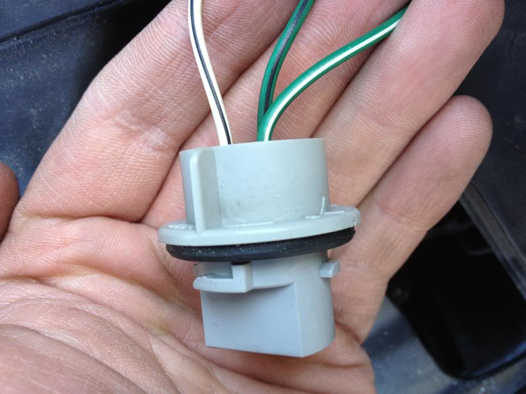
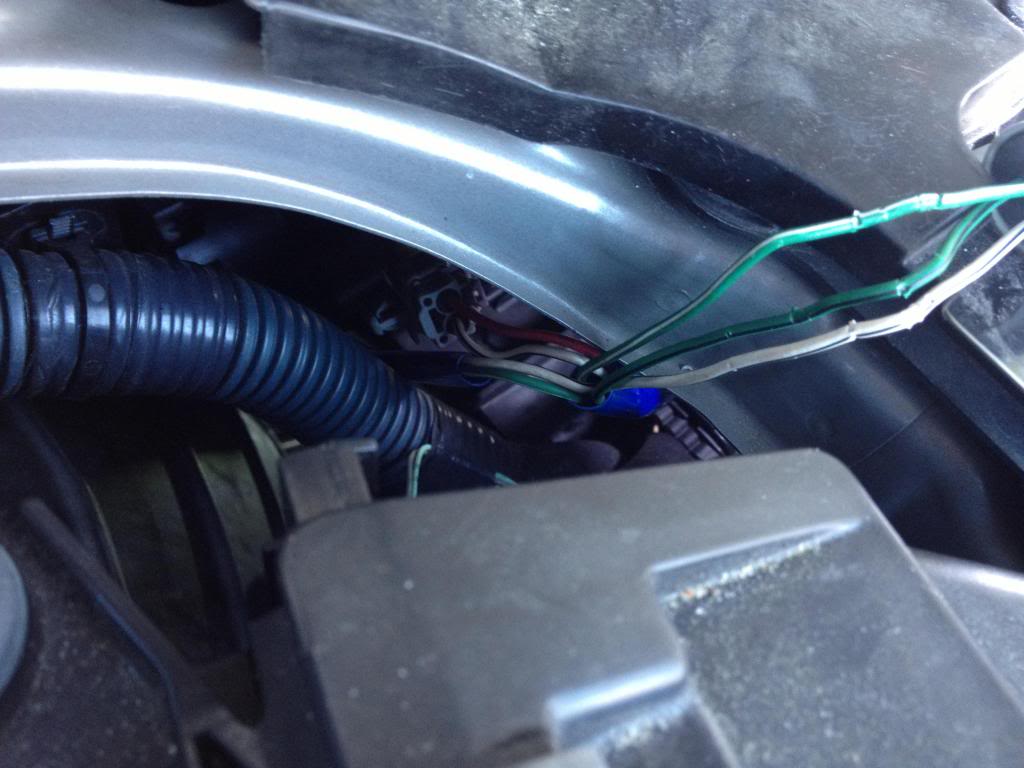
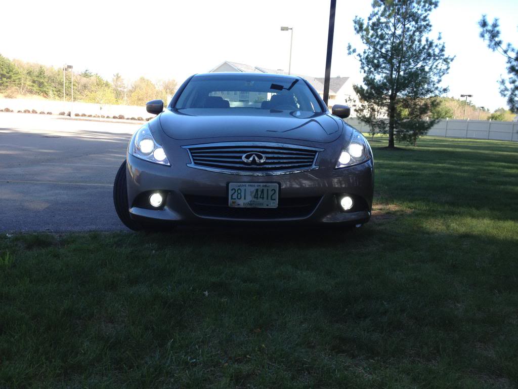
I guess when I fail inspection for it I'll have them look and see if they can do anything about it. I posted some pics below of the wires and the final product.


 12-04-2018, 05:21 PM
#11

Switchback signal/marker
I have a 2010 g37xs sedan am I able to use the switchback type bulb for the front turn signals/marker, for some reason that shows the 2010 having two separate bulbs one for turn signal one for marker 7440 bulb the 2011 using a 7444 bulb, did they change from 10 to 11?


Thread
Thread Starter
Forum
Replies
Last Post