DIY: Angel Eyes, Wiring, and TSX-R lens swap
 01-05-2014, 08:12 PM
#1


Angel Eyes, Wiring, and TSX-R lens swap
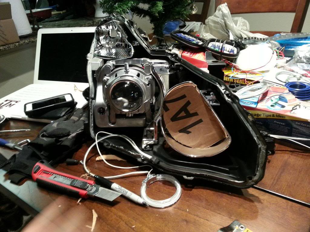
This is going to be a big one, so strap in guys. This DIY will cover brief headlight removal, opening headlights, my process for modifying them, how to create a DRL harness, and swapping in TSX-R lenses into the COUPE.
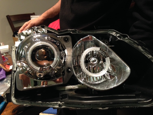
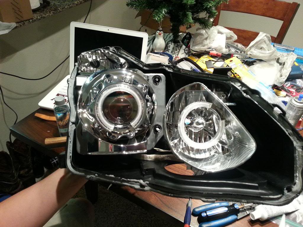
First of all, the results.
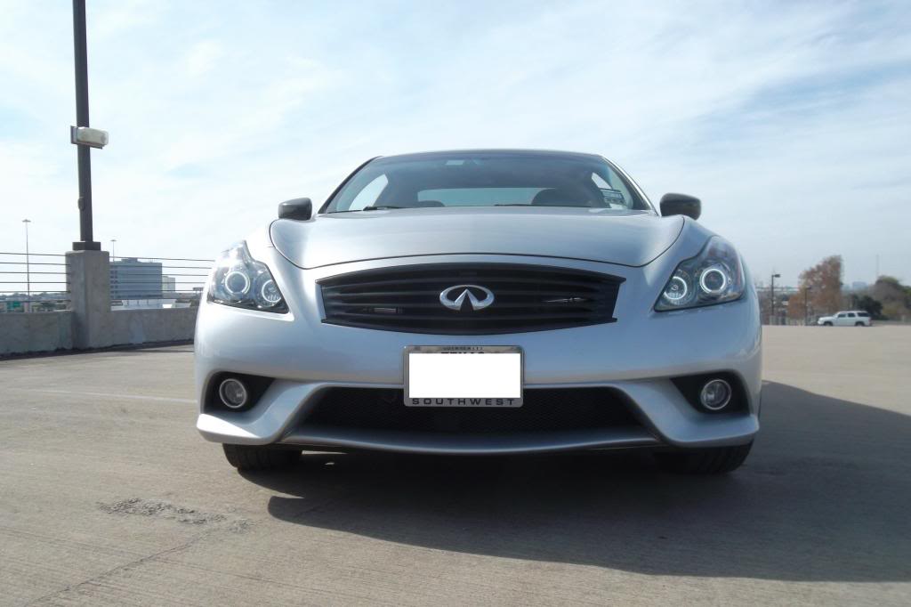
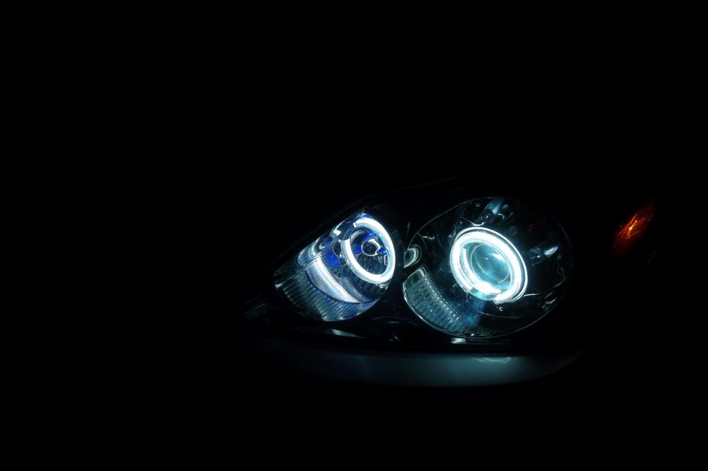
I am happy with the results. I have a gap in my lights where the wires come out, but that's just due to my angel eye light selection. Your mileage may vary.
To begin with, you can't do much headlight modding while they are still on the car. You will need to remove them. Black Betty in the DIY section has instructions to remove your headlights, but tentatively, you need to remove the bumper, and four bolts per headlight, then unplug the harness from each.
Take your headlights inside, you won't be back for a while.
Open Your Headlights
Materials:
Phillips screwdriver
Needle nose pliers
Channel lock pliers
Oven w/cookie sheet big enough to fit headlights
Trim removal tools
Gloves
Basic Process Overview:
Remove as much hardware as you can from the outside of the lights and bake them @200 degrees for 9-12 minutes on a cookie sheet.
Detailed Instructions:
1. Begin by removing all the bulbs in your headlight.
2. Starting with the turn signal bulb socket, follow and remove the necessary screws that hold the wire harness in place.
3. Remove the trim bracket from the bottom of the light and the ballast sitting underneath.
4. Undo the phillips screws that are on the perimeter of the headlight, these, in addition to the butyl glue, hold the front of the headlights onto the body.
5. By now your oven should be preheated. With the rack on the lowest setting, place 1 headlight at a time into the heated oven. I balanced the headlight on it's natural bottom, it is in the same orientation as it sits on the car.
6. Close the oven door carefully and let the headlights heat for at least 8 minutes. I did 8 the first time, and required a LOT of muscle to get the front off. 10 minutes is a good number.
7. Put your gloves on and remove the headlights. Beginning at the "outside" corner of the headlight (outside relative to where they sit on the car), use trim removal tools to gently pry open the gap between your front clear lens and the rear black housing. You'll hear some popping sounds as the glue stretches and parts. Don't be afraid to head it back up a little more if you notice you're not making any headway.
8. Once the front of one headlight is off, I'd say go ahead and mod it. I didn't see any particular benefit to opening both headlights at the same time. One at a time means you can use the other side as a template for where the wiring and bulb harnesses need to go.
Congratulations, your headlight is open. Time to get down to business.

Put In Your Angel Eyes
Materials:
4 x 72mm CCFL Rings
2 x Diode Dynamics Inverter Boards
2 x TSX-R Lenses
Nitrile gloves
Wire cutters
Needle nosed pliers
28 Gauge picture hanging wire
Power drill
1/16" bit and 5/64" bit
Electrical tape
Precision screwdriver set (phillips and flat)
Brass Punch Set (probably not necessary)
Small tack hammer or craft hammer
Windex and microfiber cloth
Small heyhole saw
Qtips
Flat, disposable surface to mix epoxy on
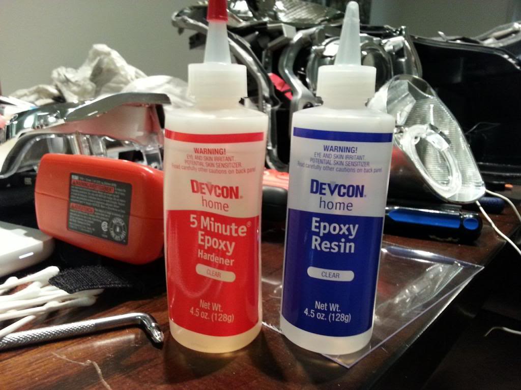
Binary, 5 minute expoxy
Really any epoxy will work, but I didn't want to sit there for 20 minutes holding a ring on to a shroud and waiting for it to cure enough to let go. I used high temp, water resistant, clear epoxy that I picked up from Lowes.
There is a very steep learning curve. The first headlight took me around 3 hours, the second took me less than 1 hour.
Basic Process Overview:
Remove the reflectors from the housing. Drill holes in the reflector to thread the wires through. Use binary epoxy to secure the rings to the side of the reflector, use picture hanging wire for a strong connection. Replace the OEM lens with the TSX-r lens, and reinstall everything. Run the wires out the back of the headlight. Button the headlights back up.
Detailed Instructions:
1. Begin by putting your gloves on, a lot of the surfaces you will be working with are not fingerprint-friendly. Take special care when working around the lenses.
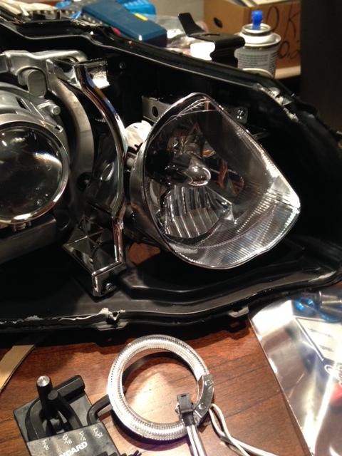
2. Remove the city light reflector. It is held in place by one screw and two ball-and-socket joints to allow it to be adjusted. Unscrew the screw, and just pull firmly to pop the reflector out of the housing.
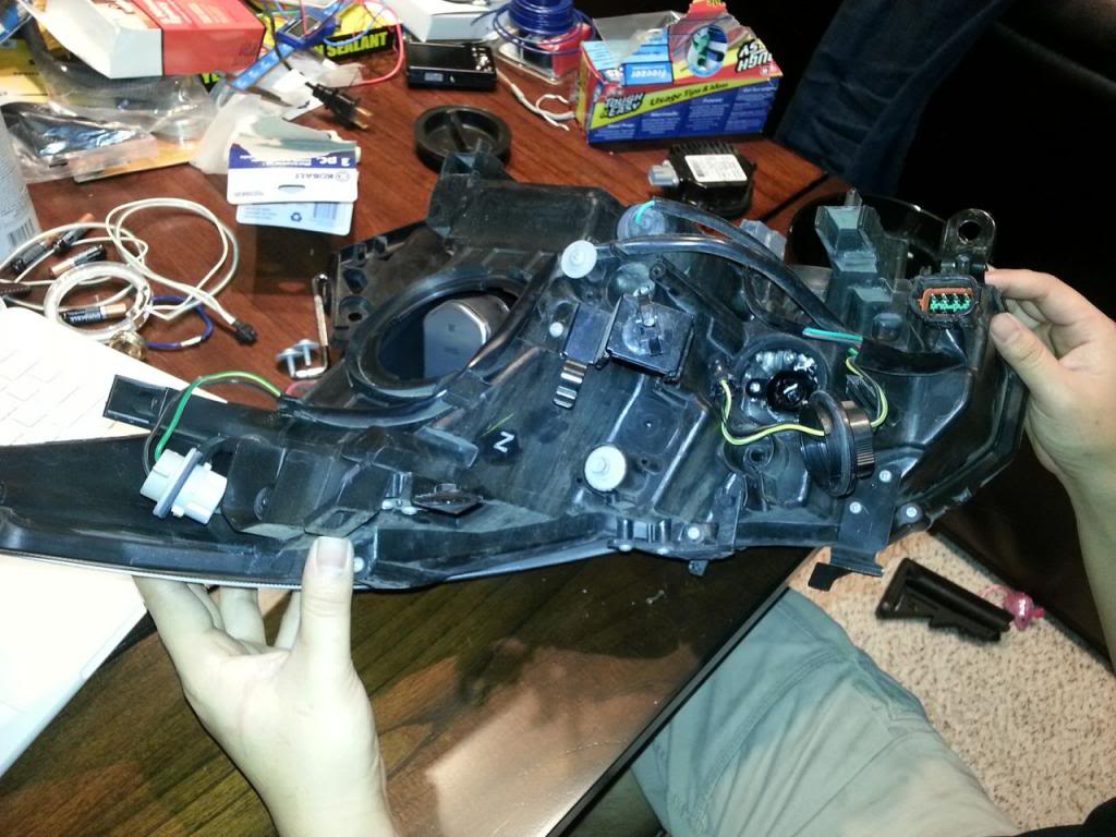
3. Start working with the city light shroud. As you can see, the reflector for the city light is not a perfect circle. It is flat along one side. This side will be obstructed by the front of the headlight anyways, so this is where we will do our work.
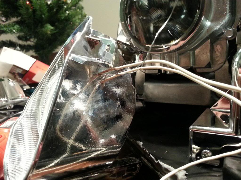
4. Figure out where you want your CCFL rings to go. My CCFL ring design had the two wires attached to the outer diameter of the ring near a gap in the cathode tube. Since I wanted as much light output as possible, I would use the non-lighted gap to attach to the side of the reflector.
5. The front of the CCFL ring lines up with the front of the miniature reflector in the center of the larger city light reflector.
6. You will be drilling four holes to attach each ring. Two of the holes will be very small and will be used to secure the ring with picture hanging wire. The other two will be used to thread the wires to the outside/rear of the reflector.
7. Figure out what hole placement works best for you. I did my holes in a very tight "X" Top and bottom holes were for the wires to exit the reflector, and were drilled with a 5/64" bit, the front and rear holes were drilled for the picture hanging wire and were drilled with a 1/16" bit.
8. Mix the binary epoxy together according to the directions. You won't need much, I used a dime sized dab of each compound to glue 1 ring in place. This stuff sets up quickly, so you'll need to re-mix as we go along.
[IMG]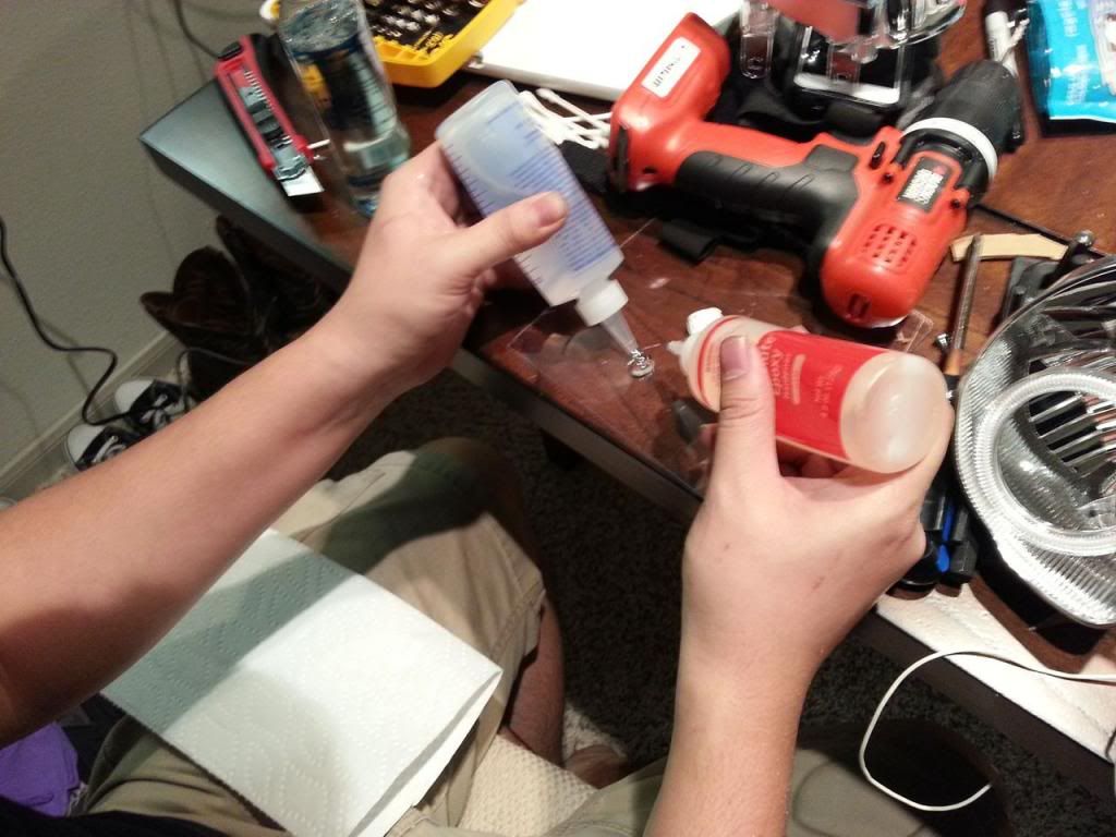 [/IMG]
9. Thread the CCFL wires out the bigger holes you drilled. Cut a 8" length of the picture hanging wire and thread it through the ring and out the holes you drilled. Gently twist the ends together just so it doesn't fall apart. You will glue it first, then tighten the wire to secure it all.
10. Use a qtip with some of the fluff torn off to pick up epoxy and transfer it to the outside of the ring and the inside of the reflector. A little goes a long way. You still have a little time to wiggle it perfectly. Use one hand to hold the ring in place and the other to begin twisting the picture hanging wire tight. You will feel it begin to take the weight of the ring soon, make sure you don't overtighten it, or it will break the wire.
11. Use a pair of needle nosed pliers to continue tightening the picture hanging wire until it is nice and tight. I left lots and lots of leftover hanging wire there for the time being. You should be able to let go of the ring now, the hanging wire will hold the ring in place until it is all cured. You're finished with the city light section, time to go to the main lens.
12. The main lens shroud is simply held on by one phillips screw on to the top. Undo it and tilt the shroud down and pull out to remove it.
First of all, the results.

I am happy with the results. I have a gap in my lights where the wires come out, but that's just due to my angel eye light selection. Your mileage may vary.
To begin with, you can't do much headlight modding while they are still on the car. You will need to remove them. Black Betty in the DIY section has instructions to remove your headlights, but tentatively, you need to remove the bumper, and four bolts per headlight, then unplug the harness from each.
Take your headlights inside, you won't be back for a while.
Open Your Headlights
Materials:
Phillips screwdriver
Needle nose pliers
Channel lock pliers
Oven w/cookie sheet big enough to fit headlights
Trim removal tools
Gloves
Basic Process Overview:
Remove as much hardware as you can from the outside of the lights and bake them @200 degrees for 9-12 minutes on a cookie sheet.
Detailed Instructions:
1. Begin by removing all the bulbs in your headlight.
2. Starting with the turn signal bulb socket, follow and remove the necessary screws that hold the wire harness in place.
3. Remove the trim bracket from the bottom of the light and the ballast sitting underneath.
4. Undo the phillips screws that are on the perimeter of the headlight, these, in addition to the butyl glue, hold the front of the headlights onto the body.
5. By now your oven should be preheated. With the rack on the lowest setting, place 1 headlight at a time into the heated oven. I balanced the headlight on it's natural bottom, it is in the same orientation as it sits on the car.
6. Close the oven door carefully and let the headlights heat for at least 8 minutes. I did 8 the first time, and required a LOT of muscle to get the front off. 10 minutes is a good number.
7. Put your gloves on and remove the headlights. Beginning at the "outside" corner of the headlight (outside relative to where they sit on the car), use trim removal tools to gently pry open the gap between your front clear lens and the rear black housing. You'll hear some popping sounds as the glue stretches and parts. Don't be afraid to head it back up a little more if you notice you're not making any headway.
8. Once the front of one headlight is off, I'd say go ahead and mod it. I didn't see any particular benefit to opening both headlights at the same time. One at a time means you can use the other side as a template for where the wiring and bulb harnesses need to go.
Congratulations, your headlight is open. Time to get down to business.
Put In Your Angel Eyes
Materials:
4 x 72mm CCFL Rings
2 x Diode Dynamics Inverter Boards
2 x TSX-R Lenses
Nitrile gloves
Wire cutters
Needle nosed pliers
28 Gauge picture hanging wire
Power drill
1/16" bit and 5/64" bit
Electrical tape
Precision screwdriver set (phillips and flat)
Brass Punch Set (probably not necessary)
Small tack hammer or craft hammer
Windex and microfiber cloth
Small heyhole saw
Qtips
Flat, disposable surface to mix epoxy on
Binary, 5 minute expoxy
Really any epoxy will work, but I didn't want to sit there for 20 minutes holding a ring on to a shroud and waiting for it to cure enough to let go. I used high temp, water resistant, clear epoxy that I picked up from Lowes.

There is a very steep learning curve. The first headlight took me around 3 hours, the second took me less than 1 hour.
Basic Process Overview:
Remove the reflectors from the housing. Drill holes in the reflector to thread the wires through. Use binary epoxy to secure the rings to the side of the reflector, use picture hanging wire for a strong connection. Replace the OEM lens with the TSX-r lens, and reinstall everything. Run the wires out the back of the headlight. Button the headlights back up.
Detailed Instructions:
1. Begin by putting your gloves on, a lot of the surfaces you will be working with are not fingerprint-friendly. Take special care when working around the lenses.
2. Remove the city light reflector. It is held in place by one screw and two ball-and-socket joints to allow it to be adjusted. Unscrew the screw, and just pull firmly to pop the reflector out of the housing.

3. Start working with the city light shroud. As you can see, the reflector for the city light is not a perfect circle. It is flat along one side. This side will be obstructed by the front of the headlight anyways, so this is where we will do our work.

4. Figure out where you want your CCFL rings to go. My CCFL ring design had the two wires attached to the outer diameter of the ring near a gap in the cathode tube. Since I wanted as much light output as possible, I would use the non-lighted gap to attach to the side of the reflector.
5. The front of the CCFL ring lines up with the front of the miniature reflector in the center of the larger city light reflector.
6. You will be drilling four holes to attach each ring. Two of the holes will be very small and will be used to secure the ring with picture hanging wire. The other two will be used to thread the wires to the outside/rear of the reflector.
7. Figure out what hole placement works best for you. I did my holes in a very tight "X" Top and bottom holes were for the wires to exit the reflector, and were drilled with a 5/64" bit, the front and rear holes were drilled for the picture hanging wire and were drilled with a 1/16" bit.

8. Mix the binary epoxy together according to the directions. You won't need much, I used a dime sized dab of each compound to glue 1 ring in place. This stuff sets up quickly, so you'll need to re-mix as we go along.
[IMG]
 [/IMG]
9. Thread the CCFL wires out the bigger holes you drilled. Cut a 8" length of the picture hanging wire and thread it through the ring and out the holes you drilled. Gently twist the ends together just so it doesn't fall apart. You will glue it first, then tighten the wire to secure it all.


10. Use a qtip with some of the fluff torn off to pick up epoxy and transfer it to the outside of the ring and the inside of the reflector. A little goes a long way. You still have a little time to wiggle it perfectly. Use one hand to hold the ring in place and the other to begin twisting the picture hanging wire tight. You will feel it begin to take the weight of the ring soon, make sure you don't overtighten it, or it will break the wire.
11. Use a pair of needle nosed pliers to continue tightening the picture hanging wire until it is nice and tight. I left lots and lots of leftover hanging wire there for the time being. You should be able to let go of the ring now, the hanging wire will hold the ring in place until it is all cured. You're finished with the city light section, time to go to the main lens.
12. The main lens shroud is simply held on by one phillips screw on to the top. Undo it and tilt the shroud down and pull out to remove it.
Last edited by GoFightNguyen; 01-06-2014 at 01:31 PM.
 01-05-2014, 08:21 PM
#2
Continued
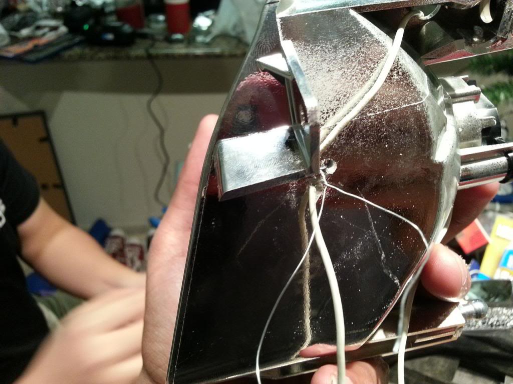
13. This one is much easier. In this case, I drilled two small diameter holes very close together on the top of the shroud to thread the picture hanging wire. The CCFL ring wires were threaded through two larger diameter holes in the bottom of the ring.
14. Go ahead and mix up your epoxy, and cut your 8" length of picture hanging wire.
15. Smear the back of the ring with epoxy. In this case, there is very little ACTUAL connection between the ring and the epoxy, so use enough to make it secure. Just make sure you keep everything on the back of the ring and off the sides where someone might see it. They'd have to be staring directly into your headlight to do so, but it's better to keep it clean.
16. Secure the ring with hanging wire and tighten it in a similar process as with the city lights.
17. Tighten your wire gently and leave it to cure. Time to worry about the lens swap.
Lens Swap:
Basic Process Overview:
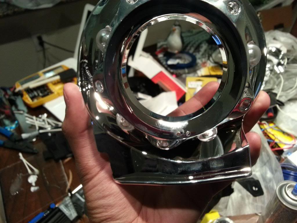
Pry the lock ring off the front of the projector housing, dump out the old lens, add the new lens with, or without spacers, reinstall the lock ring, and hammer it into the divots to secure.
Detailed Instructions:
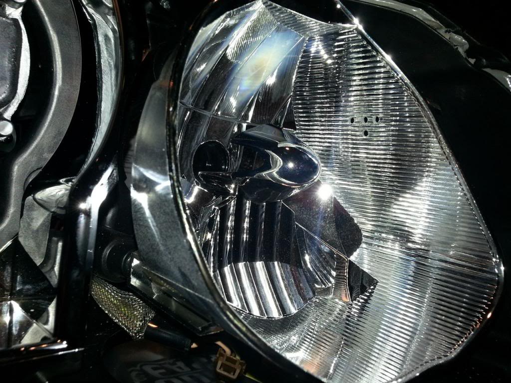
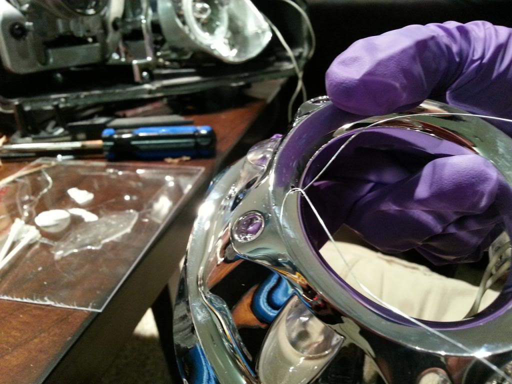
1. The lens on the coupe is secured much less.....securely (rigidly? look, I don't own a thesaurus) than it seems to be on the sedan. Just from looking at the projector housing, you can see what I mean.
2. You can see the lines molded/etched into the OEM lens. You can also see the aluminum ring that is holding the lens on. There are no screws to worry about here. As you can see, there are four divots in the projector housing, and the aluminum ring has been deformed into those divots to secure the lens to the projector housing. Are you as horrified as I am?
3. I used a small flathead screwdriver and some trim removal tools to gently pry the aluminum ring out of the divots and slide the whole assembly off. The whole process is actually pretty simple. You're going to UN-bend the metal to slip the ring off and pop the lens out.
4. Once the ring is off, the lens should just fall out. Loosening the aluminum ring at all will cause the lens to wiggle and rattle. Take your time, I don't know if you can even buy a replacement ring without buying a whole new headlight.
5. Wear gloves to make sure you don't get fingerprints on the new lens. Pull the new TSX-R lens out of the box it came in and give it a quick wipe with a clean microfiber cloth to get any dust off of it.
6. Place the new lens into the projector housing and put the aluminum ring back over it to secure it. At this point, you can add spacers behind the lens if you want, but I didn't use any.
7. I used a brass punch set and a small tack hammer I use for gunsmithing to hammer the aluminum lock ring back into the original divots. A little bit of time with a screwdriver and a hammer can net you the same results, but again, be careful.
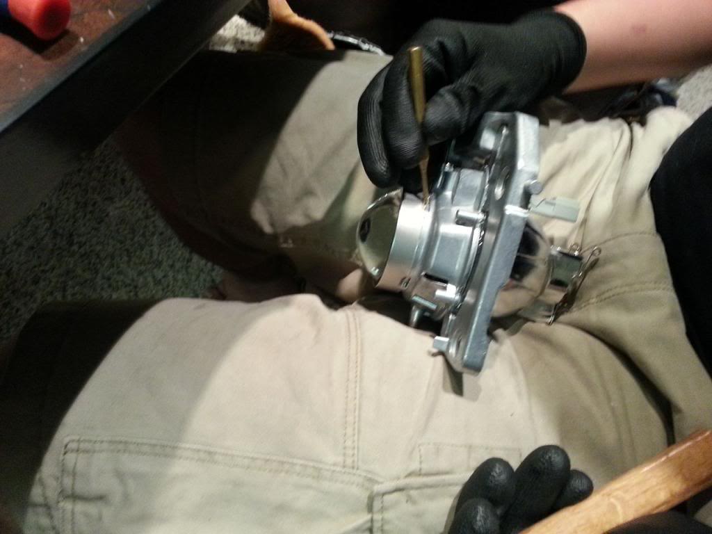
8. Make sure your lens is secure, shake the housing gently to listen for rattling and poke it with a gloved finger to see if it will move. Trust me, you do NOT want to come back and revisit this particular step. Do it once, do it right.
9. That's it, really, simple and produces some dramatic results.
Button it back up
You'll use the same tools as you did with the disassembly. Put the shrouds back in place in a reverse of the removal instructions. Clean any sawdust, fingerprints, or debris off the inside of your headlights. Once you put it back up, what's in there, will stay there. Make sure any paint or epoxy you put in has had sufficient time to dry and cure. You DO NOT want any moisture or residue bottled up in your headlights.
1. Reinstall your city light reflector, trim the excess picture hanging wire off and run the CCFL ring wires to the rear of the headlight.
2. Reinstall your main headlamp shroud, trim the picture hanging wire, screw it back in, and run the CCFL ring wires to the rear of the headlight.
3. You removed a rubber gasket earlier when you were taking off the main bulb harness. I bound the CCFL ring wires together, marked which wires corresponded to which ring, and ran them out the hole the gasket seals up.
4. Gently fit the front of the headlight back on to the main housing and try to get it as lined up as you can.
5. Heat your oven to 200 degrees again, and bake your assembly for 8 minutes or so.
6. Pull it out of the oven and gently squeeze the front and back together until the gap is back to what it was before. If you want to be extra secure, you can buy new butyl glue, clean out the old glue while it's warm, and reapply a new bead.
7. Reinstall your bulbs and wiring harness.
8. See the rubber gasket that has a green grounding wire coming out of it? Your CCFL ring wires will exit the headlight here, but you don't want them getting pinched by the gasket. Use a keyhole saw to create a cutout in the gasket hole.
9. Thread the wires out this new trench, and use a dab of silicone or epoxy to seal it back up. Reinstall the gasket and complete your resassembly.
10. If you got a diode dynamics CCFL ring and inverter boards, go ahead and connect one inverter board per headlight. Each board has 2 connections for a CCFL ring.
Congratulations, your headlight is now ready to be wired up.
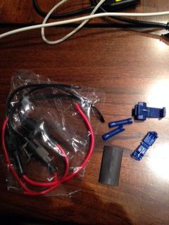
Wire Harness
I got a DRL relay from liteminder, but this harness works with virtually any relay. You can even make your own.
Materials:
Automotive wire, red, and black. I bought 15 foot rolls of each from Autozone and I didn't even use close to all of it. 16-18 gauge is probably fine.
Butt splices of appropriate size
Wire cutters
Wire strippers
Electrical tape
T-taps of appropriate gauge
4x All-weather electrical connectors
DRL relay
Fuse tap and 10A fuses
Utility Knife
Long screwdriver
Flashlight
3M double sided tape
Socket set
3/8" cable wrap protector
zip ties
Autoranging Voltmeter
Ooooookay. I just want to say that this sucked. I cannot begin to tell you how much I dislike automotive electrical work. Hopefully you can learn from my mistakes. My many, many, many mistakes.
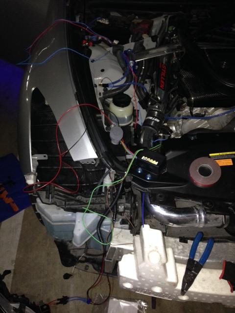
See what I mean?
Basic Process Overview:
Create Harness, troubleshoot. Cry.
Detailed Instructions:
1. Remove your bumper, there are instructions aplenty for this, so I won't go in to detail. Remove the positive AND negative terminals of your battery and make sure your car is off. If your car is somehow on after doing that, patent whatever is causing it and just pay someone to do this for you.
2. Pop your hood, and remove the battery and brake covers. Remove your windshield and upper engine bay trim. This is the same removal process as if you were going to do the mod that prevents windshield creaking. If you're having that problem, you might as well do that fix now. Basically, pop out a bunch of push-rivets, unbolt the windshield wipers, and pull the whole thing off to expose your main wiring harness boot.
3. While you're taking this apart, remove your glove compartment using the DIY available for that. If you need to change your cabin filter or swap out your glove compartment bulb, now is the time to do it.
4. Remove your fuse box cover. In the more recent coupes, the fuse box cover in question is in the left side of the drivers footwell.
It is worth pausing the DIY here and giving a general explanation for what this harness does and how it works. This, and many other headlight modification projects require +12v DC power to go into your harness. In some headlight mods, people will source that +12v DC power directly from the fuse box. (I'm looking at you, Brad).
This has the potential to do some pretty unpleasant things to your car's electrical system and is not recommended. Luckily, you have oodles and oodles of +12v DC power from your car's battery. Obviously, you can't just wire up your headlights to the battery. They would be on all the time, which would drain your battery and make you look like a d-bag. What you need is a switch that turns ON when your car is on and OFF when your car is off. This is called a relay. You can make your own, or order them online. Very simply, when the relay sees a 12v source that means your car is on, it connects your headlights to the battery and powers them on. When your car is off, the 12v source flips the relay off and the connection to the battery is broken.For this DIY, we will be using the fuse box to tell the relay the car is on, the battery to power the headlights, and the negative terminal of the battery to finish the connection on each circuit.

14. Go ahead and mix up your epoxy, and cut your 8" length of picture hanging wire.

15. Smear the back of the ring with epoxy. In this case, there is very little ACTUAL connection between the ring and the epoxy, so use enough to make it secure. Just make sure you keep everything on the back of the ring and off the sides where someone might see it. They'd have to be staring directly into your headlight to do so, but it's better to keep it clean.
16. Secure the ring with hanging wire and tighten it in a similar process as with the city lights.
17. Tighten your wire gently and leave it to cure. Time to worry about the lens swap.

Lens Swap:
Basic Process Overview:
Pry the lock ring off the front of the projector housing, dump out the old lens, add the new lens with, or without spacers, reinstall the lock ring, and hammer it into the divots to secure.
Detailed Instructions:
1. The lens on the coupe is secured much less.....securely (rigidly? look, I don't own a thesaurus) than it seems to be on the sedan. Just from looking at the projector housing, you can see what I mean.
2. You can see the lines molded/etched into the OEM lens. You can also see the aluminum ring that is holding the lens on. There are no screws to worry about here. As you can see, there are four divots in the projector housing, and the aluminum ring has been deformed into those divots to secure the lens to the projector housing. Are you as horrified as I am?
3. I used a small flathead screwdriver and some trim removal tools to gently pry the aluminum ring out of the divots and slide the whole assembly off. The whole process is actually pretty simple. You're going to UN-bend the metal to slip the ring off and pop the lens out.
4. Once the ring is off, the lens should just fall out. Loosening the aluminum ring at all will cause the lens to wiggle and rattle. Take your time, I don't know if you can even buy a replacement ring without buying a whole new headlight.
5. Wear gloves to make sure you don't get fingerprints on the new lens. Pull the new TSX-R lens out of the box it came in and give it a quick wipe with a clean microfiber cloth to get any dust off of it.
6. Place the new lens into the projector housing and put the aluminum ring back over it to secure it. At this point, you can add spacers behind the lens if you want, but I didn't use any.
7. I used a brass punch set and a small tack hammer I use for gunsmithing to hammer the aluminum lock ring back into the original divots. A little bit of time with a screwdriver and a hammer can net you the same results, but again, be careful.

8. Make sure your lens is secure, shake the housing gently to listen for rattling and poke it with a gloved finger to see if it will move. Trust me, you do NOT want to come back and revisit this particular step. Do it once, do it right.
9. That's it, really, simple and produces some dramatic results.
Button it back up
You'll use the same tools as you did with the disassembly. Put the shrouds back in place in a reverse of the removal instructions. Clean any sawdust, fingerprints, or debris off the inside of your headlights. Once you put it back up, what's in there, will stay there. Make sure any paint or epoxy you put in has had sufficient time to dry and cure. You DO NOT want any moisture or residue bottled up in your headlights.
1. Reinstall your city light reflector, trim the excess picture hanging wire off and run the CCFL ring wires to the rear of the headlight.
2. Reinstall your main headlamp shroud, trim the picture hanging wire, screw it back in, and run the CCFL ring wires to the rear of the headlight.
3. You removed a rubber gasket earlier when you were taking off the main bulb harness. I bound the CCFL ring wires together, marked which wires corresponded to which ring, and ran them out the hole the gasket seals up.
4. Gently fit the front of the headlight back on to the main housing and try to get it as lined up as you can.
5. Heat your oven to 200 degrees again, and bake your assembly for 8 minutes or so.
6. Pull it out of the oven and gently squeeze the front and back together until the gap is back to what it was before. If you want to be extra secure, you can buy new butyl glue, clean out the old glue while it's warm, and reapply a new bead.
7. Reinstall your bulbs and wiring harness.
8. See the rubber gasket that has a green grounding wire coming out of it? Your CCFL ring wires will exit the headlight here, but you don't want them getting pinched by the gasket. Use a keyhole saw to create a cutout in the gasket hole.
9. Thread the wires out this new trench, and use a dab of silicone or epoxy to seal it back up. Reinstall the gasket and complete your resassembly.
10. If you got a diode dynamics CCFL ring and inverter boards, go ahead and connect one inverter board per headlight. Each board has 2 connections for a CCFL ring.
Congratulations, your headlight is now ready to be wired up.
Wire Harness
I got a DRL relay from liteminder, but this harness works with virtually any relay. You can even make your own.
Materials:
Automotive wire, red, and black. I bought 15 foot rolls of each from Autozone and I didn't even use close to all of it. 16-18 gauge is probably fine.
Butt splices of appropriate size
Wire cutters
Wire strippers
Electrical tape
T-taps of appropriate gauge
4x All-weather electrical connectors
DRL relay
Fuse tap and 10A fuses
Utility Knife
Long screwdriver
Flashlight
3M double sided tape
Socket set
3/8" cable wrap protector
zip ties
Autoranging Voltmeter
Ooooookay. I just want to say that this sucked. I cannot begin to tell you how much I dislike automotive electrical work. Hopefully you can learn from my mistakes. My many, many, many mistakes.

See what I mean?
Basic Process Overview:
Create Harness, troubleshoot. Cry.
Detailed Instructions:
1. Remove your bumper, there are instructions aplenty for this, so I won't go in to detail. Remove the positive AND negative terminals of your battery and make sure your car is off. If your car is somehow on after doing that, patent whatever is causing it and just pay someone to do this for you.
2. Pop your hood, and remove the battery and brake covers. Remove your windshield and upper engine bay trim. This is the same removal process as if you were going to do the mod that prevents windshield creaking. If you're having that problem, you might as well do that fix now. Basically, pop out a bunch of push-rivets, unbolt the windshield wipers, and pull the whole thing off to expose your main wiring harness boot.
3. While you're taking this apart, remove your glove compartment using the DIY available for that. If you need to change your cabin filter or swap out your glove compartment bulb, now is the time to do it.
4. Remove your fuse box cover. In the more recent coupes, the fuse box cover in question is in the left side of the drivers footwell.
It is worth pausing the DIY here and giving a general explanation for what this harness does and how it works. This, and many other headlight modification projects require +12v DC power to go into your harness. In some headlight mods, people will source that +12v DC power directly from the fuse box. (I'm looking at you, Brad).
This has the potential to do some pretty unpleasant things to your car's electrical system and is not recommended. Luckily, you have oodles and oodles of +12v DC power from your car's battery. Obviously, you can't just wire up your headlights to the battery. They would be on all the time, which would drain your battery and make you look like a d-bag. What you need is a switch that turns ON when your car is on and OFF when your car is off. This is called a relay. You can make your own, or order them online. Very simply, when the relay sees a 12v source that means your car is on, it connects your headlights to the battery and powers them on. When your car is off, the 12v source flips the relay off and the connection to the battery is broken.For this DIY, we will be using the fuse box to tell the relay the car is on, the battery to power the headlights, and the negative terminal of the battery to finish the connection on each circuit.
Last edited by GoFightNguyen; 01-06-2014 at 01:36 PM.
The following 5 users liked this post by GoFightNguyen:
blnewt (01-05-2014),
foxktm90 (09-15-2014),
FRChilln (01-31-2014),
RMusiq (07-18-2014),
twin_snails (05-06-2015)
01-05-2014, 08:21 PM
#3
5. First, figure out how your DRL relay works. Mine has a blue wire (+12v fuse) and a brown wire (ground) that turn the relay on, or off. It also has a red (+12v battery) and green wire (headlights) that provides power to your headlight mod. From the CCFL rings, we need a ground wire to complete the circuit back to the negative terminal of the battery. Don't get it? You soon will.
6. The easiest thing to do first is tell your relay when to turn on and off. To do that, you need to find a fuse that puts out +12v when your car is on, and 0v when it is not. Your fuse cover has a diagram on the back that tells you which fuse to tap via an appropriately named "fuse tap". In my case, it was on the right side of the fuse box, and the seventh fuse down. I tapped here, and put 2x10A fuses in the tap. Use a voltmeter to verify that this fuse puts out 12v before you finish connecting everything up.
7. Excellent, now we have +12v power to tell our relay the status of the car. How are we going to get the wire from the relay all the way to the inside of the driver footwell? We can go through the main wiring harness boot.
8. You removed your windshield and upper engine bay trim to expose the main wiring harness boot. It looks like this (picture is linked to BLnewt's DIY for wiring fog lights). Thanks Brad!
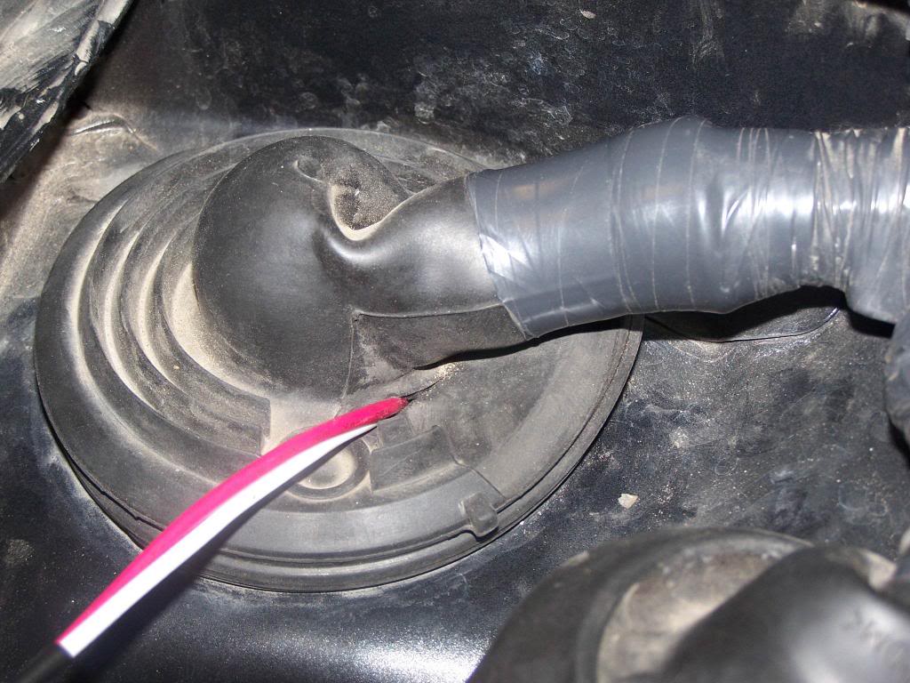
Interior work:
9. Use a utility knife to create a small slit in the rubber, be careful not to nick or damage any of the wires. Attach the end of a long piece of wire (I just spooled out the whole roll and cut to size, but you probably need something like 7 feet) to a long screwdriver. I used some electrical tape to secure it.
10. Push the screwdriver/wire assembly through the rubber boot and watch it appear magically into your interior. You DID remove the glove compartment like I told you too, didn't you?
11. Remove the wire from the screwdriver and pull about 4 feet of slack into the interior of the car.
12. Use a flashlight to look on the left of the passenger footwell. You can see a space under the dash and above the floor where you can pass a wire through. A flashlight from the drivers side footwell will make the space obvious. You can use your long screwdriver trick to pass the wire from the passenger footwell to the drivers side, or you can just feed it through.
13. Run the wire behind the left driver footwell trim and connect your wire to the fuse tap.
14. Tuck the wire under the carpet and insulation, pull the extra back out the car, you can reinstall your glove compartment now. Congratulations, you're done with the interior of the car. You can put the upper engine bay trim back on and resecure your push rivets.
Engine Bay Work:
Basic Process Overview:
Connect your headlights to the relay and ground, wire the relay to the battery and ground, wire the relay to the fuse box.
Detailed Instructions:
1. The first thing you need to do is get your headlights ready to connect to the harness you will build. By now you probably want to go back inside, so we'll talk about how to wire up your headlights in the comfort of your heated/cooled home.
2. You should have two connectors apiece coming out of your headlight. The connectors should attach to your inverter boards. The CCFL rings, unlike most headlight mods, run off Alternating Current. You WILL need an inverter board to change the 12V DC current from the battery to AC power. It took me several hours of troubleshooting before I stumbled on this gem. If you use an LED ring, you don't need an inverter board.
3. The inverter boards each have a red and black wire. I used butt splices to connect these wires to a connector. This way, when I assemble/remove headlights, I can just disconnect the headlight from the wiring harness without having to worry about mucking about with cutting wires.
4. I don't think much water gets in to your engine bay, but due to the location of the headlights/grille, it's not a bad idea to use all weather connectors. They're a buck apiece from DiodeDynamics, I would just get 10 or so (male AND female) to make cover your bases.
5. I heat shrank my connections and butt splices just to be doubly sure everything was nice and tidy. Trust me, troubleshooting connections is not how you want to spend your new years.
6. Your headlights should now have 2 connectors apiece leading from the inverter boards.
7. On the passenger side headlight, take the corresponding connector that mates with whatever you chose to splice onto your headlight, and wire it for a t-tap. A T-tap allows you to pull power from a wire without having to worry about splicing or soldering. Picture explanation below:
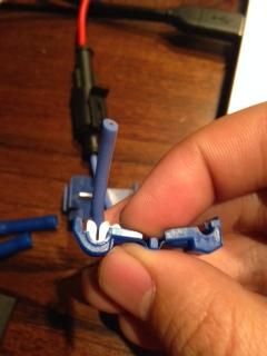
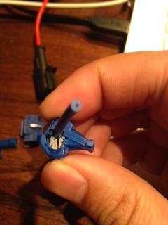

A single power and ground wire will be leaving the DRL relay. The drivers side headlight will connect to the ends of those wires, the passenger side will just t-tap into the appropriate wire. This is the easiest way I could think of to make this work. I'll draw up a proper wiring diagram and upload it later.
8. You've done as much work as you can in the comfort of home. At this point, you should have two female connectors for each headlight, as well as two un-stripped male connectors (driver), and two male connectors that have a T-tap connector attached to them. Now it's back outside to see if you're as good (or bad) at wiring as you think you are!
9. Run the appropriate lengths of wire from your DRL relay to the headlights. I decided to connect to the relay and have enough wire to travel down to the passenger wheel well splash guard, back up to the radiator shroud, over to the drivers side, down to the drivers side wheel well splash guard, and back up to the drivers side headlight. This gives plenty of slack, and provides a little bit of wiggle room if you mess up a connection and need to cut and splice later.
10. Use a butt splice to connect your the corresponding connectors to the end of the wire in the drivers side splash guard. This is where your drivers side headlights will connect in. You should have at least enough slack in the wire to pull the headlight a foot away from the car while still connected.
11. Measure the best place to T-tap your passenger side headlight, measure twice, and tap it in. Use your loose t-tap connector to tap into the power and ground wires. You COULD just wire the headlights straight into the t-tap, but that requires you to pull pretty hard, and you don't want to accidentally dislodge any connections while you're fiddling around in such a tight space.
12. Connect your passenger headlight into the wire harness.
13. Both of the ground wires from the relay go to the same point on my car. I have a grounding wire kit that attaches to the passenger side chassis before running to the negative terminal of the battery. You can certainly run your negative wires all the way back to the negative terminal of the battery, but I had a grounding point handy. I used a ring terminal to connect both grounding wires from the relay to this grounding point. See the DIY Your own Grounding Wires thread to see where this point is.
14. The relay I have came with a positive wire complete with a fused ring terminal. This just slips on to the +12v DC RED BATTERY TERMINAL and will provide power to the headlights when the relay is on.
Please be careful when mucking around with your battery.
15. A +12 wire comes out from the relay and connects to the (red in my case) power wire for the harness I made previously.
16. You should be all wired up now. You probably want to hook everything up and make sure your lights work. To recap:
+12v fuse tap leads from the fuse box in the drivers footwell to the relay. -12v ground leads from the relay to the negative terminal of the battery. +12v wire leads from the positive terminal of the battery to the relay. +12v wire leads from the relay to the RED wire in your harness. The passenger headlight t-taps into the harness, and the drivers headlight straight connects to the end of the harness. The negative BLACK wire in your harness connects the negative headlight connections to the negative terminal of your battery.
17. Hold your breath, sacrifice a goat, and turn your car on. The rings should light up. If they are, you are a king among men (or a queen among women). If not, troubleshoot connections. Use a voltmeter starting from your fuse box and make sure you have +12v DC at every point in the positive side of the circuit.
Did You Fall From Heaven, Angel? Achievement Unlocked.
6. The easiest thing to do first is tell your relay when to turn on and off. To do that, you need to find a fuse that puts out +12v when your car is on, and 0v when it is not. Your fuse cover has a diagram on the back that tells you which fuse to tap via an appropriately named "fuse tap". In my case, it was on the right side of the fuse box, and the seventh fuse down. I tapped here, and put 2x10A fuses in the tap. Use a voltmeter to verify that this fuse puts out 12v before you finish connecting everything up.
7. Excellent, now we have +12v power to tell our relay the status of the car. How are we going to get the wire from the relay all the way to the inside of the driver footwell? We can go through the main wiring harness boot.
8. You removed your windshield and upper engine bay trim to expose the main wiring harness boot. It looks like this (picture is linked to BLnewt's DIY for wiring fog lights). Thanks Brad!

Interior work:
9. Use a utility knife to create a small slit in the rubber, be careful not to nick or damage any of the wires. Attach the end of a long piece of wire (I just spooled out the whole roll and cut to size, but you probably need something like 7 feet) to a long screwdriver. I used some electrical tape to secure it.
10. Push the screwdriver/wire assembly through the rubber boot and watch it appear magically into your interior. You DID remove the glove compartment like I told you too, didn't you?
11. Remove the wire from the screwdriver and pull about 4 feet of slack into the interior of the car.
12. Use a flashlight to look on the left of the passenger footwell. You can see a space under the dash and above the floor where you can pass a wire through. A flashlight from the drivers side footwell will make the space obvious. You can use your long screwdriver trick to pass the wire from the passenger footwell to the drivers side, or you can just feed it through.
13. Run the wire behind the left driver footwell trim and connect your wire to the fuse tap.
14. Tuck the wire under the carpet and insulation, pull the extra back out the car, you can reinstall your glove compartment now. Congratulations, you're done with the interior of the car. You can put the upper engine bay trim back on and resecure your push rivets.
Engine Bay Work:
Basic Process Overview:
Connect your headlights to the relay and ground, wire the relay to the battery and ground, wire the relay to the fuse box.
Detailed Instructions:
1. The first thing you need to do is get your headlights ready to connect to the harness you will build. By now you probably want to go back inside, so we'll talk about how to wire up your headlights in the comfort of your heated/cooled home.
2. You should have two connectors apiece coming out of your headlight. The connectors should attach to your inverter boards. The CCFL rings, unlike most headlight mods, run off Alternating Current. You WILL need an inverter board to change the 12V DC current from the battery to AC power. It took me several hours of troubleshooting before I stumbled on this gem. If you use an LED ring, you don't need an inverter board.
3. The inverter boards each have a red and black wire. I used butt splices to connect these wires to a connector. This way, when I assemble/remove headlights, I can just disconnect the headlight from the wiring harness without having to worry about mucking about with cutting wires.
4. I don't think much water gets in to your engine bay, but due to the location of the headlights/grille, it's not a bad idea to use all weather connectors. They're a buck apiece from DiodeDynamics, I would just get 10 or so (male AND female) to make cover your bases.
5. I heat shrank my connections and butt splices just to be doubly sure everything was nice and tidy. Trust me, troubleshooting connections is not how you want to spend your new years.
6. Your headlights should now have 2 connectors apiece leading from the inverter boards.
7. On the passenger side headlight, take the corresponding connector that mates with whatever you chose to splice onto your headlight, and wire it for a t-tap. A T-tap allows you to pull power from a wire without having to worry about splicing or soldering. Picture explanation below:


A single power and ground wire will be leaving the DRL relay. The drivers side headlight will connect to the ends of those wires, the passenger side will just t-tap into the appropriate wire. This is the easiest way I could think of to make this work. I'll draw up a proper wiring diagram and upload it later.
8. You've done as much work as you can in the comfort of home. At this point, you should have two female connectors for each headlight, as well as two un-stripped male connectors (driver), and two male connectors that have a T-tap connector attached to them. Now it's back outside to see if you're as good (or bad) at wiring as you think you are!
9. Run the appropriate lengths of wire from your DRL relay to the headlights. I decided to connect to the relay and have enough wire to travel down to the passenger wheel well splash guard, back up to the radiator shroud, over to the drivers side, down to the drivers side wheel well splash guard, and back up to the drivers side headlight. This gives plenty of slack, and provides a little bit of wiggle room if you mess up a connection and need to cut and splice later.
10. Use a butt splice to connect your the corresponding connectors to the end of the wire in the drivers side splash guard. This is where your drivers side headlights will connect in. You should have at least enough slack in the wire to pull the headlight a foot away from the car while still connected.
11. Measure the best place to T-tap your passenger side headlight, measure twice, and tap it in. Use your loose t-tap connector to tap into the power and ground wires. You COULD just wire the headlights straight into the t-tap, but that requires you to pull pretty hard, and you don't want to accidentally dislodge any connections while you're fiddling around in such a tight space.
12. Connect your passenger headlight into the wire harness.
13. Both of the ground wires from the relay go to the same point on my car. I have a grounding wire kit that attaches to the passenger side chassis before running to the negative terminal of the battery. You can certainly run your negative wires all the way back to the negative terminal of the battery, but I had a grounding point handy. I used a ring terminal to connect both grounding wires from the relay to this grounding point. See the DIY Your own Grounding Wires thread to see where this point is.
14. The relay I have came with a positive wire complete with a fused ring terminal. This just slips on to the +12v DC RED BATTERY TERMINAL and will provide power to the headlights when the relay is on.
Please be careful when mucking around with your battery.
15. A +12 wire comes out from the relay and connects to the (red in my case) power wire for the harness I made previously.
16. You should be all wired up now. You probably want to hook everything up and make sure your lights work. To recap:
+12v fuse tap leads from the fuse box in the drivers footwell to the relay. -12v ground leads from the relay to the negative terminal of the battery. +12v wire leads from the positive terminal of the battery to the relay. +12v wire leads from the relay to the RED wire in your harness. The passenger headlight t-taps into the harness, and the drivers headlight straight connects to the end of the harness. The negative BLACK wire in your harness connects the negative headlight connections to the negative terminal of your battery.
17. Hold your breath, sacrifice a goat, and turn your car on. The rings should light up. If they are, you are a king among men (or a queen among women). If not, troubleshoot connections. Use a voltmeter starting from your fuse box and make sure you have +12v DC at every point in the positive side of the circuit.
Did You Fall From Heaven, Angel? Achievement Unlocked.
Last edited by GoFightNguyen; 01-05-2014 at 10:02 PM.
01-05-2014, 08:54 PM
#5
Congratu-****ing-lations. You beautiful animal. You did it. Break out the bubbly!!
Time to clean up and tidy up your wiring to guard against vibration, weather, and ugliness.
Clean Up
Basic Process Overview:
Cover the exposed wires with cable wrap, secure the cable wrap with electrical tape, zip tie the loose wires into tidy bundles, put everything back on.
Detailed Instructions:
1. Use your cable wrap and measure out to fit the lengths of exposed wires between connections.
2. Beginning from the drivers side headlight. Wrap your bundle of wires that directly exit the headlight in electrical tape, there's not enough space here to use cable wrap. Just make sure that you get nice insulation and that they don't rub anything hot or rough.
3. Use cable wrap to protect your harness leading from the drivers side to the passenger side. The route should go from the driver headlight down into the driver splash guard well (this gives you enough slack to pull out and disconnect the headlight in the future), up the radiator core support, and under the radiator shroud. Use Zipties to secure the cable wrap to the core support. Once you get under the radiator shroud, you can see there's the hood release cable and the horn wire harness. Just follow that to the passenger side.
4. Again, dive down the radiator core support into the passenger side wheel well splash guard....thingy, and wrap, cover, and ziptie appropriately. I ziptie every foot or so.
5. IMPORTANT. Since you have a t-tap here, not a regular connection, I just folded the wire back on itself and cable wrapped that package. This is just a cleaner way to keep everything nice and neat. Basically, in the passenger side wheel well, you should have 4 wires cable wrapped instead of the 2 you were protecting in the drivers side. Not really a big deal, do it however you see fit, see if I care.
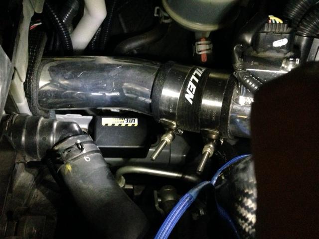
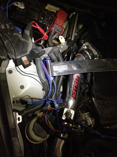
6. Continue wrapping and protecting everything all the way back up. I mounted my DRL relay box to the spot where my stock airboxes used to go. I have stillen Gen 3 intakes now, which leaves a convenient flat spot to mount my relay on.
7. If you didn't before, you can run wires into the battery compartment through the cable wrap already provided in the stock OEM wiring harness.
8. That's about it, really. Check again to make sure your headlight rings work, then go ahead and reinstall them. Your rings should be on when the car starts up, and off when you flip the headlights on. Some DRL relays come with a "width" wire, this wire just measures current going to an existing circuit. When that current turns on, the relay will turn off. Other DRL relays have a logic circuit that measures draw on your battery. It's up to you to research how exactly your DRL works.
9. Check one more time before you put your bumper back on that the headlights function correctly. Plug them all together, check it AGAIN, and put your bumper back on. Get a flashlight and follow your wire harness from the battery to the headlights again. Check and make sure your wires aren't getting pinched, bent, or rubbed. It is a good idea to recheck this every few thousand miles.
And that's it. You've got a sick pair of quad angel eyes. It took me 3 days to do this, but you can probably do it in two regular days or 1 REALLY long day if you have all the materials. Hopefully this helped you out. I would rate this DIY as an 8/10 difficulty. I had zero headlight experience prior to this, but if I can do it, you can do it. If you didn't notice, I referenced a lot of other DIY's that you might want to take care of while you're in there. If, like me, you've already done those DIY's, then this should be old hat to get back and remove the necessary pieces. Be safe when messing with electrical work, wear gloves to protect yourself and delicate components, and don't rush things. As always, feel free to PM me if you have specific questions and I'll help as best I can. I'll be posting links to the components I bought, and a future post in this thread will sum up the estimated total cost, as well as tips and tricks that might help future DIYers. Please let me know what you think of the final result, as well as your experiences when you try this. I'm always looking to improve my DIY's, if I should change something, or it isn't clear, let me know.
Cheers,
Anthony
Thanks to MoNyTx for lending a hand and documenting the whole thing, and the guys in the various threads lending advice on what stuff to get for my mods.
Time to clean up and tidy up your wiring to guard against vibration, weather, and ugliness.
Clean Up
Basic Process Overview:
Cover the exposed wires with cable wrap, secure the cable wrap with electrical tape, zip tie the loose wires into tidy bundles, put everything back on.
Detailed Instructions:
1. Use your cable wrap and measure out to fit the lengths of exposed wires between connections.
2. Beginning from the drivers side headlight. Wrap your bundle of wires that directly exit the headlight in electrical tape, there's not enough space here to use cable wrap. Just make sure that you get nice insulation and that they don't rub anything hot or rough.
3. Use cable wrap to protect your harness leading from the drivers side to the passenger side. The route should go from the driver headlight down into the driver splash guard well (this gives you enough slack to pull out and disconnect the headlight in the future), up the radiator core support, and under the radiator shroud. Use Zipties to secure the cable wrap to the core support. Once you get under the radiator shroud, you can see there's the hood release cable and the horn wire harness. Just follow that to the passenger side.
4. Again, dive down the radiator core support into the passenger side wheel well splash guard....thingy, and wrap, cover, and ziptie appropriately. I ziptie every foot or so.
5. IMPORTANT. Since you have a t-tap here, not a regular connection, I just folded the wire back on itself and cable wrapped that package. This is just a cleaner way to keep everything nice and neat. Basically, in the passenger side wheel well, you should have 4 wires cable wrapped instead of the 2 you were protecting in the drivers side. Not really a big deal, do it however you see fit, see if I care.
6. Continue wrapping and protecting everything all the way back up. I mounted my DRL relay box to the spot where my stock airboxes used to go. I have stillen Gen 3 intakes now, which leaves a convenient flat spot to mount my relay on.

7. If you didn't before, you can run wires into the battery compartment through the cable wrap already provided in the stock OEM wiring harness.

8. That's about it, really. Check again to make sure your headlight rings work, then go ahead and reinstall them. Your rings should be on when the car starts up, and off when you flip the headlights on. Some DRL relays come with a "width" wire, this wire just measures current going to an existing circuit. When that current turns on, the relay will turn off. Other DRL relays have a logic circuit that measures draw on your battery. It's up to you to research how exactly your DRL works.
9. Check one more time before you put your bumper back on that the headlights function correctly. Plug them all together, check it AGAIN, and put your bumper back on. Get a flashlight and follow your wire harness from the battery to the headlights again. Check and make sure your wires aren't getting pinched, bent, or rubbed. It is a good idea to recheck this every few thousand miles.
And that's it. You've got a sick pair of quad angel eyes. It took me 3 days to do this, but you can probably do it in two regular days or 1 REALLY long day if you have all the materials. Hopefully this helped you out. I would rate this DIY as an 8/10 difficulty. I had zero headlight experience prior to this, but if I can do it, you can do it. If you didn't notice, I referenced a lot of other DIY's that you might want to take care of while you're in there. If, like me, you've already done those DIY's, then this should be old hat to get back and remove the necessary pieces. Be safe when messing with electrical work, wear gloves to protect yourself and delicate components, and don't rush things. As always, feel free to PM me if you have specific questions and I'll help as best I can. I'll be posting links to the components I bought, and a future post in this thread will sum up the estimated total cost, as well as tips and tricks that might help future DIYers. Please let me know what you think of the final result, as well as your experiences when you try this. I'm always looking to improve my DIY's, if I should change something, or it isn't clear, let me know.
Cheers,
Anthony
Thanks to MoNyTx for lending a hand and documenting the whole thing, and the guys in the various threads lending advice on what stuff to get for my mods.
Last edited by GoFightNguyen; 01-05-2014 at 11:17 PM.
The following 3 users liked this post by GoFightNguyen:
01-05-2014, 08:59 PM
#6
This post is gonna be for troubleshooting, tips, and advice.
It's been a couple months now since I did the swap and everything is staying exactly where I left it. I haven't noticed any condensation inside the headlights, so it looks like I lucked out. I've got butyl glue if it ever happens. This was a really fun project, possibly my favorite DIY I've ever done on my G37.
A few weeks ago, I noticed that my passenger side angel eyes were both off. They would not turn back on, but the angel eyes on the drivers side were still lit. I decided to troubleshoot a little bit. Luckily, I had an AC circuit tester handy and checked the wires leading from the inverter board to the passenger angel eyes.
The passenger side was not receiving power, but a voltmeter indicated that the inverter WAS. That means I had a bad inverter. I suspect it was probably due to exposure to moisture causing it to burn out, but I had a pretty good run. All I had to do was unplug the old one and add new. Easy peasy, didn't have to even remove the bumper.
Last edited by GoFightNguyen; 01-20-2015 at 03:42 PM.
01-05-2014, 09:17 PM
#7

Anthony, I must say you really do a great job w/ explaining the DIY, I just skimmed through it but was enough to know that you should do this more often. Great that you took the time to detail the whole process so well and thanks for adding this valuable resource.
Oh, and your results kick as$!
Oh, and your results kick as$!
The following users liked this post:
GoFightNguyen (01-05-2014)
Trending Topics
 01-06-2014, 07:43 PM
#11

Not my thing. It's an Infiniti and angel eyes are BMW. I also feel like LED running lights are being way too overplayed by every manufacturer and that it's starting to look ridiculous. Like they're putting LEDs in them just to have them in them.
With that said, I also skimmed through and the workmanship seems to be alright, so props for that.
With that said, I also skimmed through and the workmanship seems to be alright, so props for that.
01-06-2014, 07:56 PM
#12
Not my thing. It's an Infiniti and angel eyes are BMW. I also feel like LED running lights are being way too overplayed by every manufacturer and that it's starting to look ridiculous. Like they're putting LEDs in them just to have them in them. With that said, I also skimmed through and the workmanship seems to be alright, so props for that.
It's not for everyone, but I feel like some people don't do it because sending it is expensive and there aren't instructions for it.

The following users liked this post:
GoFightNguyen (01-08-2014)

The following users liked this post:
GoFightNguyen (01-08-2014)
01-09-2014, 09:24 AM
#15

Do you have or know of any pic comparison of the OEM lenses vs the TSX-R lenses? The OEM headlights on the G are just OK IMO so I'd like to improve them if possible.