
DIY: Grounding kits made simple, step by step guide to making your own!

Thread Starter
Premier Member
iTrader: (17)
Joined: Apr 2008
Posts: 1,357
Likes: 46
From: Peoria, AZ
Grounding kits made simple, step by step guide to making your own!
This guide will allow you to make your own grounding kit. These instructions will work for 2nd Gen G35 sedan, 08-XX G37 coupes, 09-XX G37 Sedans and 350/370 Z's. Please note the layouts may not be 100% identical between models, but you should be able to adjust and make these instructions work. By following these instructions, you will have every thing you need to make and install your own grounding kit that will help with car audio quality, as well as firm up those transmission shifts and fix lag in 5AT and 7AT coupes and sedans.
Items you will need:
12 ft. of 8 gauge oxygen free copper cable
6 individual 8 gauge ring terminals
3 individual 4 gauge ring terminals
Crimping tool and wire stripper
some zip ties for neatness, if you desire (I didn't use any)
Please note that all measurements in the photos are taken from the crimping point of the terminals and not from the end of the terminals themselves. The total amount of wiring used is 136 inches, so having 12 feet will allow you 8 inches of extra wiring to make sure you have enough.
Better to be slightly long in measuring than to have wires that are too short!!!
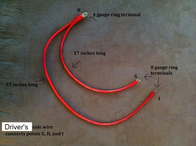
The kit is broken down into 3 wires: the drivers side wire, passenger side wire, and single connecting cable.
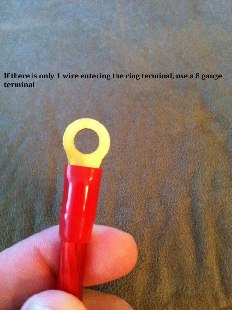
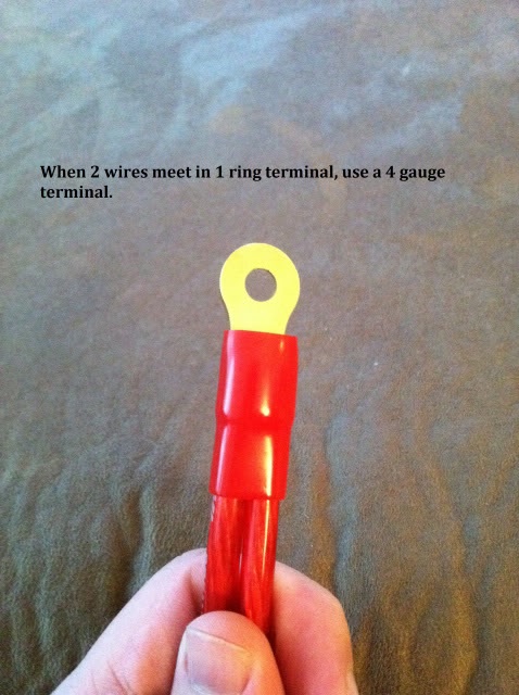
You'll note that there are 2 different sizes in ring terminals. This is explained here:
Use these next photo's to identify the length of each cable and connection, as well as which terminal goes to which connection point. There is a total of 9 connections, labeled A,B,C,D,E,F,G,H,I. You can also choose to go off course and mount additional wires to anywhere you want a strong ground signal. Some choose to add throttle body grounds, and some ground the ECU directly. It's all up to you! This instructions are for just a basic grounding kit that gets the job done!
MAKING THE WIRES
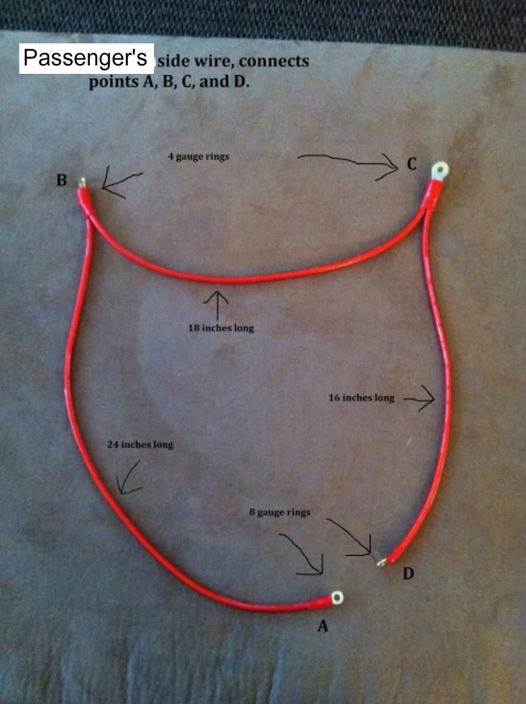
Passenger's side wire lengths and construction:
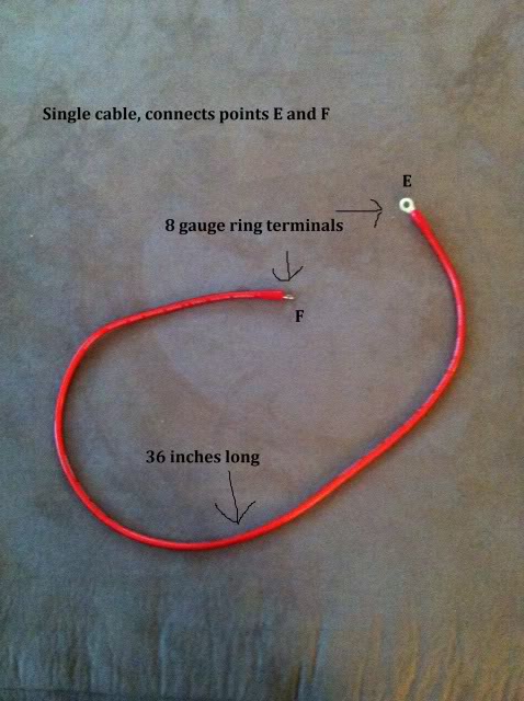
Connecting Cable:
Driver's side cable:
After you construct your 3 cables in the specified lengths, follow these installation instructions to enjoy your creation!
INSTALLATION:
Items you will need:
Ratchet, 10mm socket, extension if desired, 10mm wrench, 12mm socket.
Step 1. Detach the negative battery terminal from the battery.
Step 2. Remove the engine shroud and set it aside.
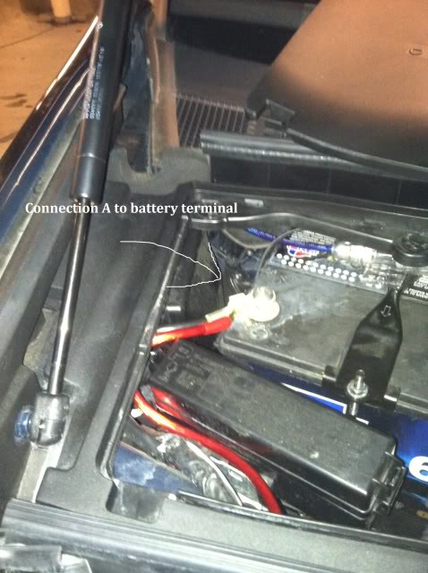
Step 3. Attach connection terminal A on the passenger side wire to the negative battery terminal. You can simply force the wire through the existing wire loom leading into the battery box. Wait to connect the wire to the batter until the end of the install.
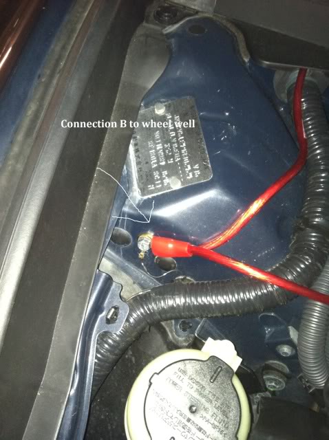
Step 4. Attach connection terminal B to the passenger's side wheel well bolt where there is already wires connected.
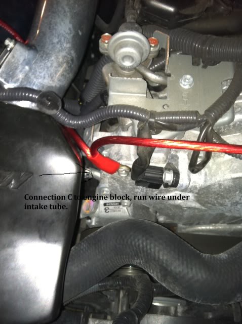
Step 5. Attach connection terminal C to the engine block corner next to intake. Make sure to run the wires under the intake tube.
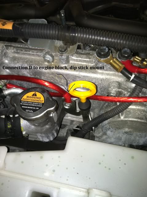
Step 6. Attach connection terminal D to the front of the engine using the dipstick mount. Passenger side wire is now complete!
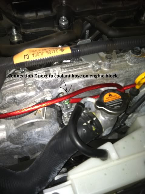
Step 7. Using the single connecting cable, attach connection terminal E to the engine block bolt behind the coolant hose:
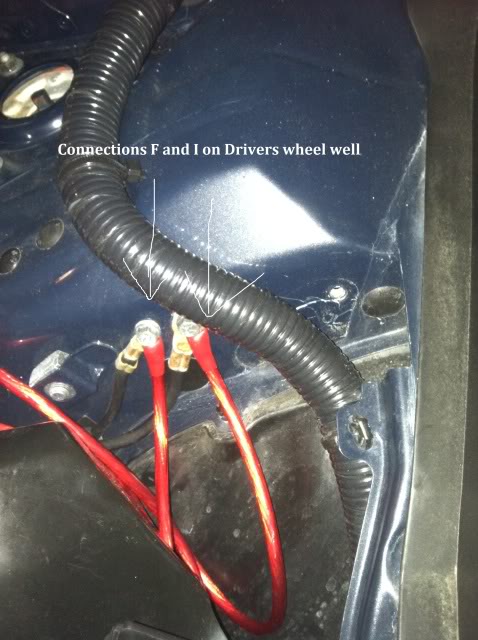
Step 8. Connect terminal F to the bolt on the drivers side wheel well, making sure to tuck the wire under the driver's side intake tube. Single cable is now complete!
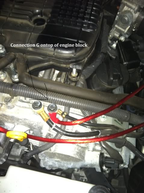
Step 9. Using the Driver's side cable, attach connection terminal G to the top of the engine block where there are wires already connected:
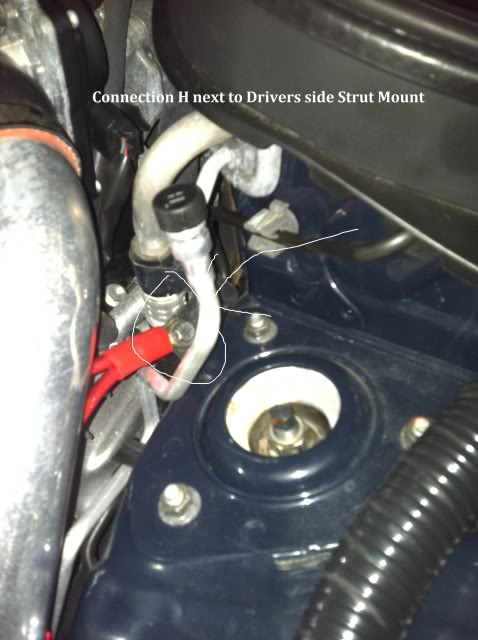
Step 10. Attach connection terminal H to the mount on the wheel well next to the driver's side strut, across from the intake/throttle body. Make sure to run the wires under the intake tube.
Step 11. Attach connection terminal I next to connection F on the drivers side wheel well where there are already wires grounded. This completes the driver's side wire!!
Step 12. Connect connection A from the passenger side wire to the battery terminal, make sure all connections on all wires are tight, and then replace battery box cover.
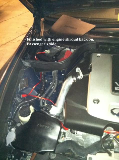
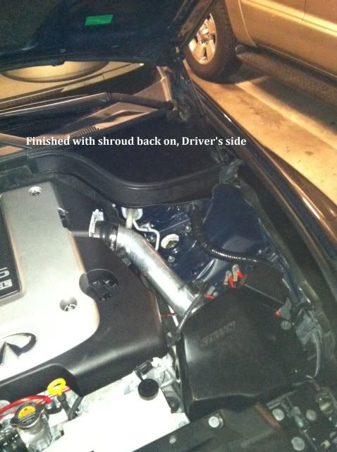
Step 13. Replace engine shroud cover, make sure all wires are tucked, secure, and not in the way of anything.
YOUR JOBS DONE, TIME TO ENJOY TRANSMISSION AND AUDIO IMPROVEMENTS!!!!!
RESULTS
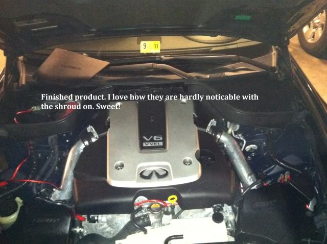
Most owners notice an immediate improvement in audio sound. Audio levels seem louder. I noticed this first hand and was very impressed. Owners also report improvements in Automatic transmission shifting. The lag between shifts in DS mode are dramatically improved, and shifts are firm and tight. It's also an added bonus that the wires look pretty cool, but if you don't want them to be an eye sore, tuck and zip-tie them away.
Items you will need:
12 ft. of 8 gauge oxygen free copper cable
6 individual 8 gauge ring terminals
3 individual 4 gauge ring terminals
Crimping tool and wire stripper
some zip ties for neatness, if you desire (I didn't use any)
Please note that all measurements in the photos are taken from the crimping point of the terminals and not from the end of the terminals themselves. The total amount of wiring used is 136 inches, so having 12 feet will allow you 8 inches of extra wiring to make sure you have enough.
Better to be slightly long in measuring than to have wires that are too short!!!
The kit is broken down into 3 wires: the drivers side wire, passenger side wire, and single connecting cable.
You'll note that there are 2 different sizes in ring terminals. This is explained here:
Use these next photo's to identify the length of each cable and connection, as well as which terminal goes to which connection point. There is a total of 9 connections, labeled A,B,C,D,E,F,G,H,I. You can also choose to go off course and mount additional wires to anywhere you want a strong ground signal. Some choose to add throttle body grounds, and some ground the ECU directly. It's all up to you! This instructions are for just a basic grounding kit that gets the job done!
MAKING THE WIRES
Passenger's side wire lengths and construction:
Connecting Cable:
Driver's side cable:
After you construct your 3 cables in the specified lengths, follow these installation instructions to enjoy your creation!
INSTALLATION:
Items you will need:
Ratchet, 10mm socket, extension if desired, 10mm wrench, 12mm socket.
Step 1. Detach the negative battery terminal from the battery.
Step 2. Remove the engine shroud and set it aside.
Step 3. Attach connection terminal A on the passenger side wire to the negative battery terminal. You can simply force the wire through the existing wire loom leading into the battery box. Wait to connect the wire to the batter until the end of the install.
Step 4. Attach connection terminal B to the passenger's side wheel well bolt where there is already wires connected.
Step 5. Attach connection terminal C to the engine block corner next to intake. Make sure to run the wires under the intake tube.
Step 6. Attach connection terminal D to the front of the engine using the dipstick mount. Passenger side wire is now complete!
Step 7. Using the single connecting cable, attach connection terminal E to the engine block bolt behind the coolant hose:
Step 8. Connect terminal F to the bolt on the drivers side wheel well, making sure to tuck the wire under the driver's side intake tube. Single cable is now complete!
Step 9. Using the Driver's side cable, attach connection terminal G to the top of the engine block where there are wires already connected:
Step 10. Attach connection terminal H to the mount on the wheel well next to the driver's side strut, across from the intake/throttle body. Make sure to run the wires under the intake tube.
Step 11. Attach connection terminal I next to connection F on the drivers side wheel well where there are already wires grounded. This completes the driver's side wire!!
Step 12. Connect connection A from the passenger side wire to the battery terminal, make sure all connections on all wires are tight, and then replace battery box cover.
Step 13. Replace engine shroud cover, make sure all wires are tucked, secure, and not in the way of anything.
YOUR JOBS DONE, TIME TO ENJOY TRANSMISSION AND AUDIO IMPROVEMENTS!!!!!
RESULTS
Most owners notice an immediate improvement in audio sound. Audio levels seem louder. I noticed this first hand and was very impressed. Owners also report improvements in Automatic transmission shifting. The lag between shifts in DS mode are dramatically improved, and shifts are firm and tight. It's also an added bonus that the wires look pretty cool, but if you don't want them to be an eye sore, tuck and zip-tie them away.
Last edited by AZg37; Apr 20, 2011 at 11:31 PM.

Popular Reply
Apr 24, 2011, 06:28 PM
Thread Starter
Premier Member
iTrader: (17)
Joined: Apr 2008
Posts: 1,357
Likes: 46
From: Peoria, AZ
Can we please not get into a debate on this DIY thread I created? If you think grounding kits are crap, cool, then don't make or install one. If you want one, now you have the steps to make and install it. Simple as that.


Thread Starter
Premier Member
iTrader: (17)
Joined: Apr 2008
Posts: 1,357
Likes: 46
From: Peoria, AZ
This should work for 2nd gen G35 sedan, G37 sedans, and G37 coupes. The layout may not be 100% identical, but the kit should still work. These photos were taken on my 09 G37 sedan.


Thread Starter
Premier Member
iTrader: (17)
Joined: Apr 2008
Posts: 1,357
Likes: 46
From: Peoria, AZ
You can pick up the supplies from many different places. Lowes or Home Depot sell wire by the foot, or you can pick up spools of it on ebay for cheap. The terminals can be found at a hardware store, online, or car audio places because they are used for stereo installations.

The hardest part of this is getting the right lengths lol.
GREAT DIY. New sticky.
Trending Topics
 hows the f.i? couldnt remember your screenname at first.
the local automotive store near my house is all straight up hustle but i just checked their website and they dont have any of those oxygem free 8 gauge cable
I used 4 ga. Usually can find it anywhere, but do what you gotta do I suppose. If you check out that site genuinedealz.com I think they can make them for you for extremely cheap if you give them the lengths. They even have all of the supplies needed. Very cheap too.


Thread Starter
Premier Member
iTrader: (17)
Joined: Apr 2008
Posts: 1,357
Likes: 46
From: Peoria, AZ
I personally disagree. While manually shifting in DS mode the car has noticeable change in lag between shifting gears. If you disagree, that's your opinion, but don't state that grounding kits do nothing like it's a fact. I installed grounding kits on both my G's and saw the same results. It's not a must, and I really only recommend it to 5AT and 7AT owners who are either audio enthusiasts or spirited drivers who enjoy DS mode, but hate trying to time your shifts because of the delay.