
DIY: NavTool

Thread Starter
Average Joe
Joined: Sep 2015
Posts: 170
Likes: 51
From: Indiana
NavTool
I recently installed the NavTool interface on my 2008 G37S Coupe. My car didn't have navigation or the backup camera options on it from the factory, so I decided to add them via the aftermarket. I can add information about my wireless backup camera setup after this if anyone is interested, as I want this part to focus on just the NavTool installation itself.
This is the NavTool module:
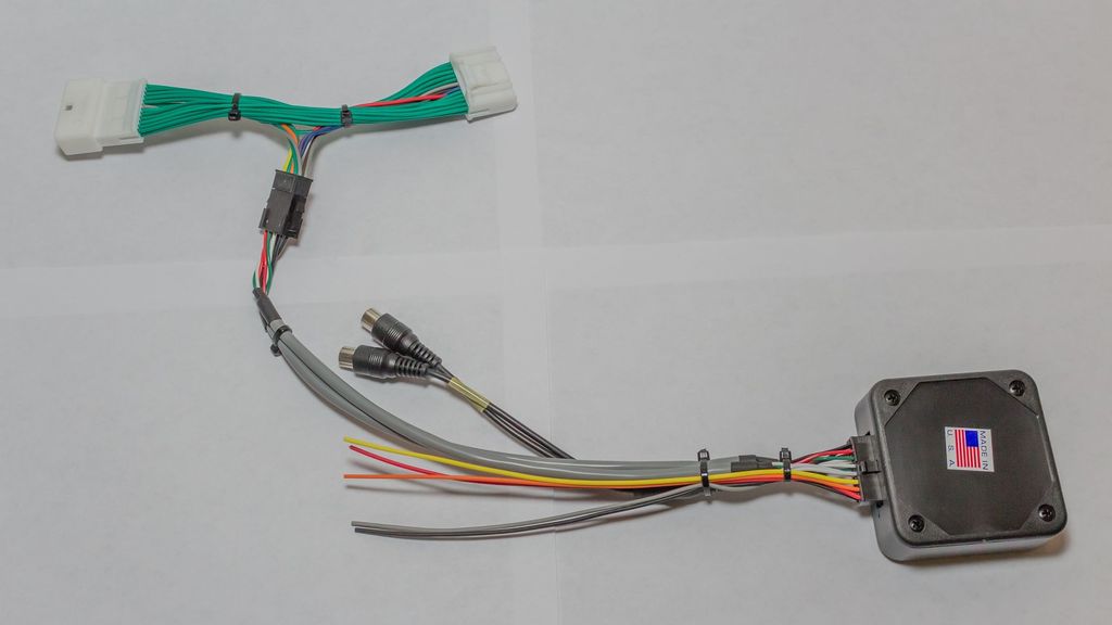
It has two video inputs, several wires that I will call out individually, a vehicle specific LCD screen harness, and the box which houses the PCB that controls everything.
The wires are as follows:
Red- +12V accessory power (I tapped into the power port that is in the center console)
Black- Chassis ground (Also tapped into the power port)
Grey- Emergency brake (needs to see ground to allow video 1 to display)
Orange- Reverse light (when this wire sees 12 Volts, it will trigger video 2 to display automatically)
Yellow- Mode switch (This wire will go to a SPST NO momentary switch, the other tab on the switch will go to a 12V source)
With all of that out of the way here are the tools you'll need to get the job done:
Phillips screwdriver
Wire strippers
Drill (bit size will depend on the size of your mode switch)
Extra wire (18 Gauge is plenty big enough)
Soldering iron (or crimp connectors)
2 T-Taps
Shrink tube or electrical tape
Heat gun or lighter
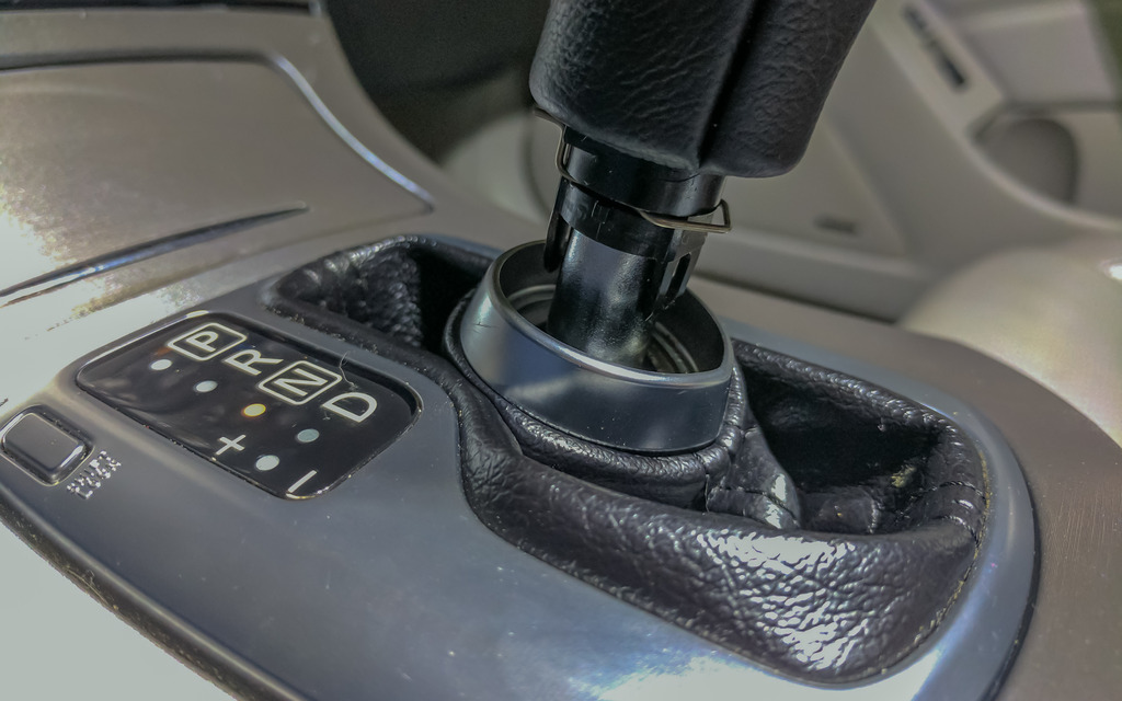
The first thing you'll need to do is remove the shifter bezel and cupholder. Open the center console lid, then pull up on the outside edges of the cup holder module. It is only held in place by plastic clips. It will start to pop out, and when it does the edge of the shifter bezel will pop up with it.

The easiest way I have found to remove the shifter bezel is to first put the vehicle in Neutral. Make sure the parking brake is on so the car doesn't roll. Pull down on the shift boot, remove the clip holding the shift **** on, then pull the shift **** off.
You can then rotate the part of the bezel closest to the rear of the car upward, then back to free it from the radio bezel clips. You can then access the two plugs that will need to be disconnected to completely remove it.
Next, you'll remove the two screws at the bottom of the radio bezel. You'll then rotate the bottom of the bezel upward then pull down to release it from the clips on the top. There will be 4 connectors on the back of this bezel that will need to be released to remove it completely.
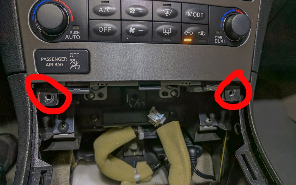
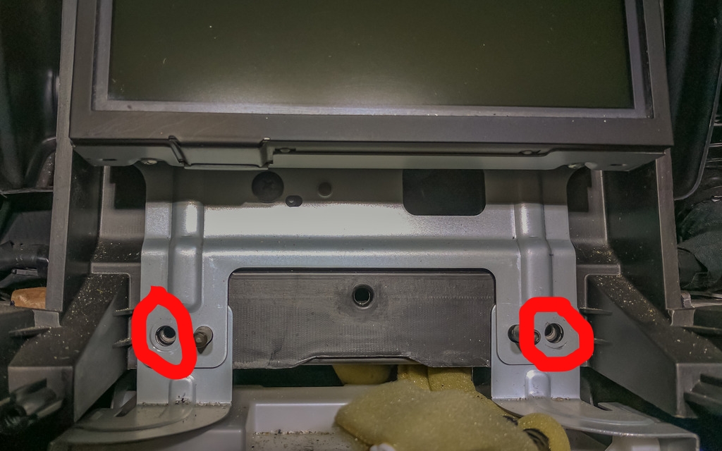
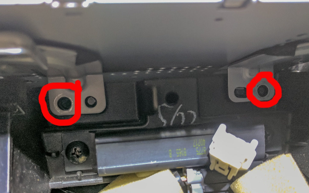
The next piece to go is the surround for the screen. There are two more screws to remove, then this piece slides straight out.
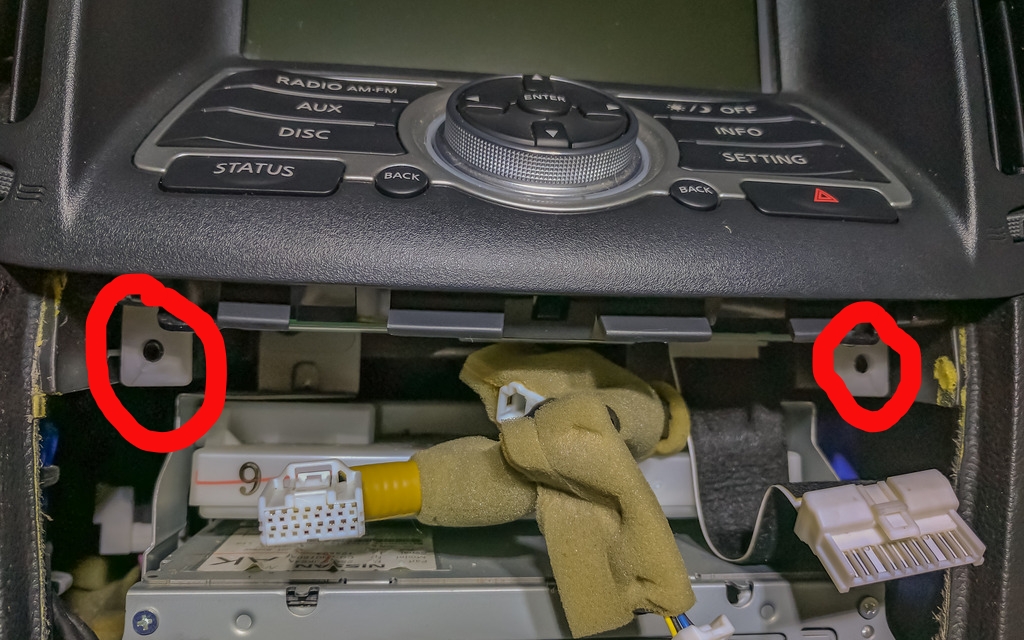
Now we remove the screen. There are two screws on the bottom to remove, then the bottom of the metal frame rotates toward the rear of the car, then downward; much like the other pieces have been removed. There are three connectors on the back of this module that will need to be removed.
I cut the zip ties on the NavTool to give me more slack on the 5 colored wires and the video inputs that I will need to be connecting after I get the box situated.
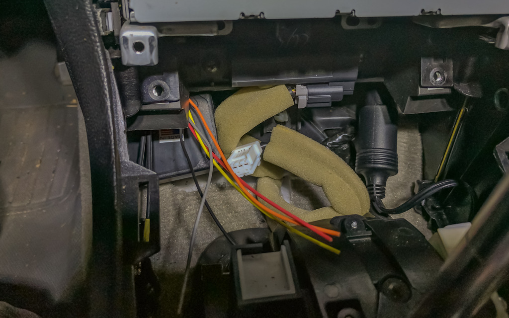
The next thing I did was pull out the CD changer module. I did this so I could run the wiring for the Navtool back behind everything and the box itself would sit down below everything else. It's kind of difficult to picture it but I tried to show where I ran it.
Two screws holding the CD unit in place. after removing them, pull the unit out a couple of inches to give space to run the box and wiring down.
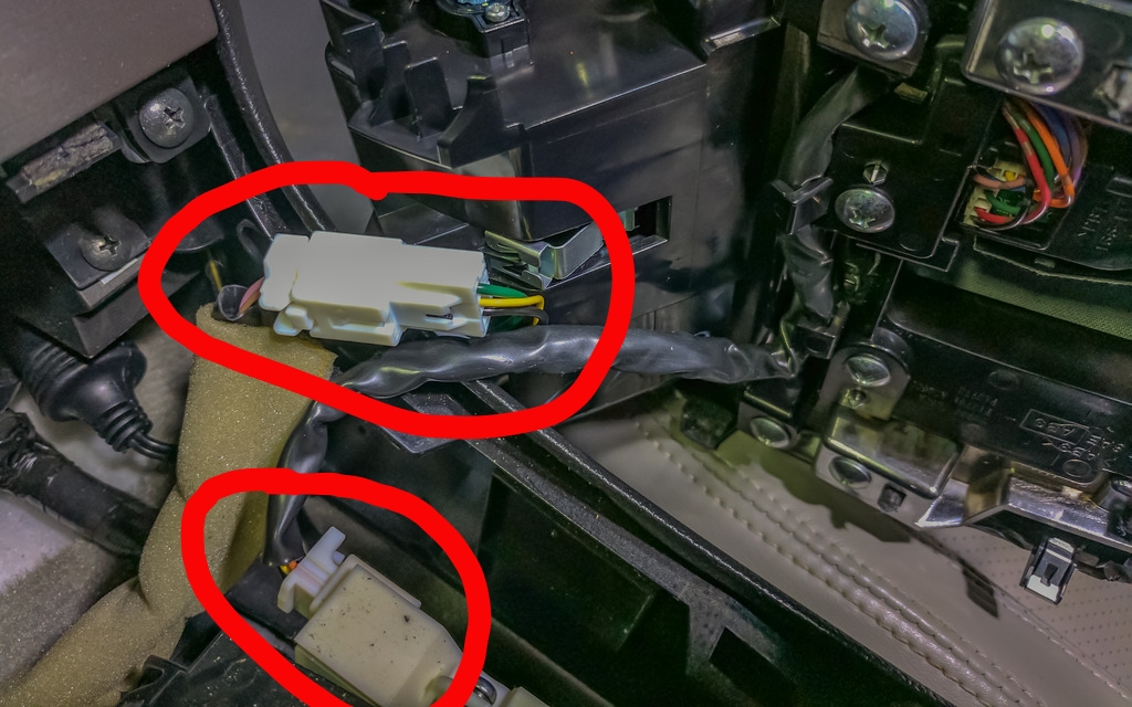
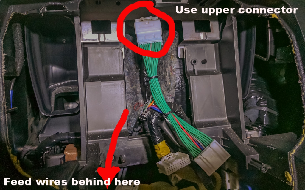
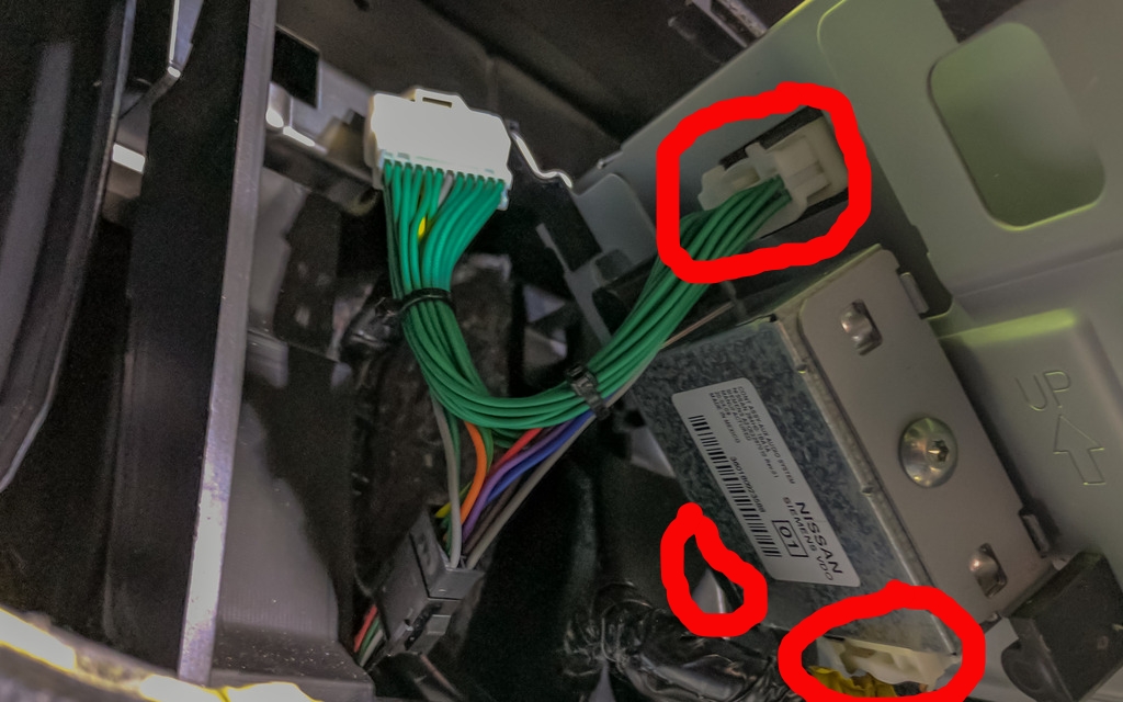
Before dropping everything through, connect one end of the green PNP harness into the upper connector that was unplugged from the screen. *Note* The lower connector that was plugged into the module behind the screen is the same, be sure to use the correct connector.
After running the box and wires down, I got the colored wires and video connectors situated so I can run them where they need to go. At this point, you can replace the screws for the CD unit.
You can now replace the screen. First connect the other end of the green PNP harness into the back of the LCD, as well as the two connectors on the module behind the screen. The screen surround can also now be replaced.
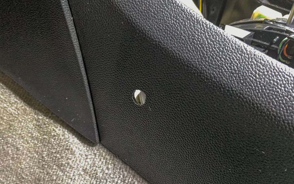
Now it's time to install the mode switching button. I drilled a hole in the plastic on the side of the console.
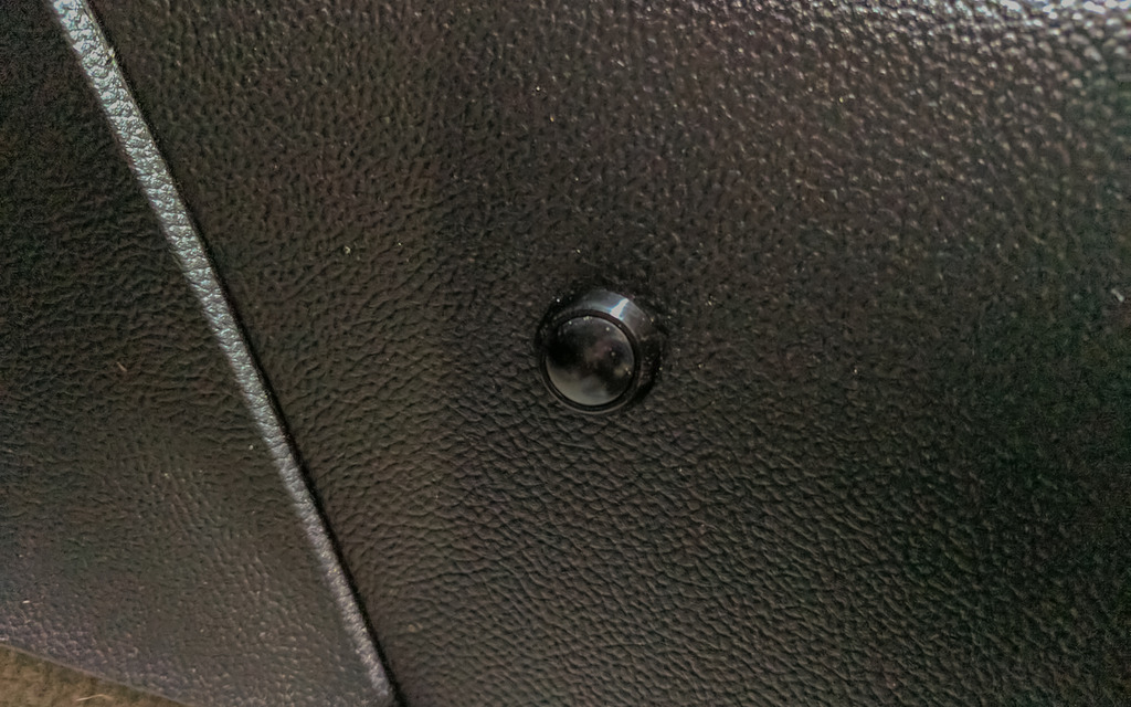
Button in place:
Now it's time to start connecting the colored wires! Here's a diagram I made of where they go:
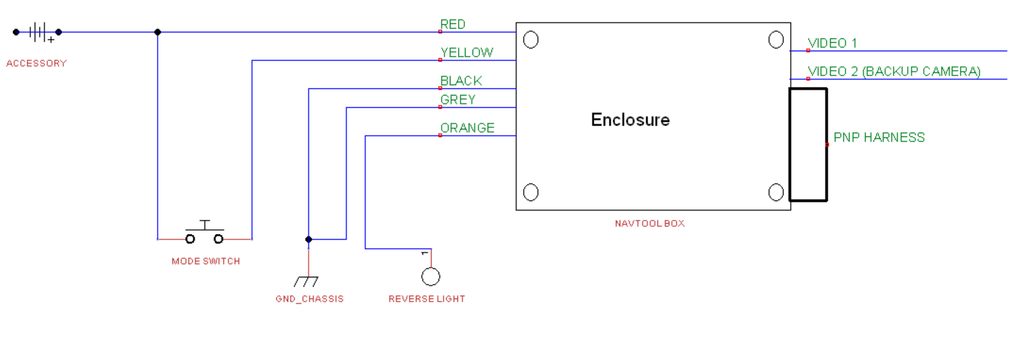
I tapped into the Yellow (12VDC) and Black (Ground) wires on the power port that is in the center console.
The Black and Grey box wires were stripped and twisted together, then soldered to an extension wire and T-Tapped into the black power port wire. The Red box wire and an extension wire from the switch (Green in this case) are soldered to an extension wire then T-Tapped into the Yellow wire from the power port. The yellow box wire is inserted into the other post on the switch.
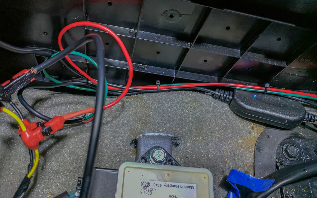
The Orange box wire hasn't been hooked up yet. It needs to be tapped into a source that carries 12VDC when the vehicle is placed into reverse. This is so the video 2 input automatically turns on and off when you're backing up. I'm still looking for an easier way to do this than running the wire all the way to the reverse lights.
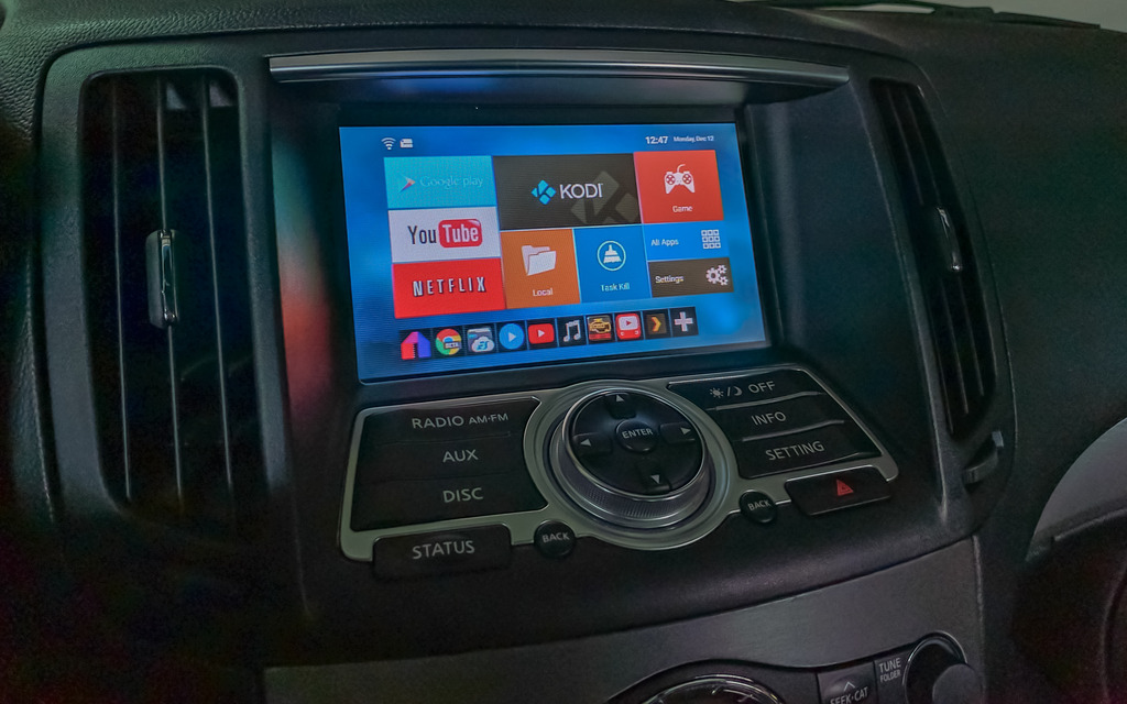
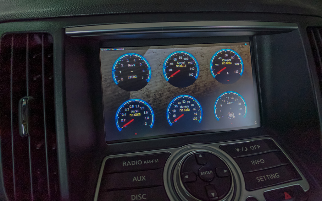
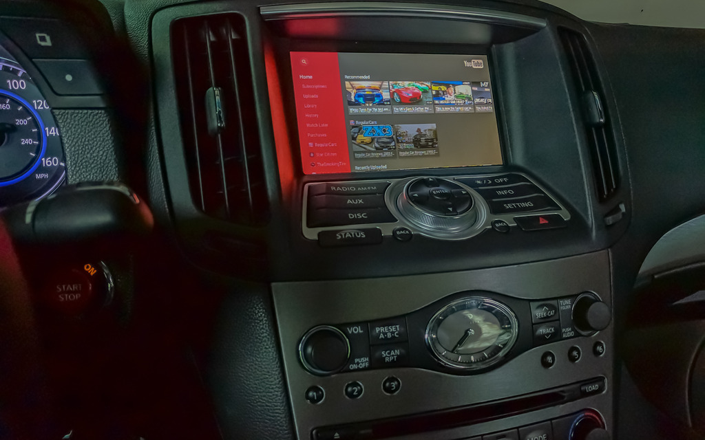
At this point, you should hook up your video inputs and test to make sure they work. A short press of the button will switch between Video 1 and Video 2. A long press will return the screen to the factory display. If everything works correctly, then you're ready to button everything else back up.
After everything is back in place double-check that it's working, then enjoy the fruits of your labor!
This is the NavTool module:

It has two video inputs, several wires that I will call out individually, a vehicle specific LCD screen harness, and the box which houses the PCB that controls everything.
The wires are as follows:
Red- +12V accessory power (I tapped into the power port that is in the center console)
Black- Chassis ground (Also tapped into the power port)
Grey- Emergency brake (needs to see ground to allow video 1 to display)
Orange- Reverse light (when this wire sees 12 Volts, it will trigger video 2 to display automatically)
Yellow- Mode switch (This wire will go to a SPST NO momentary switch, the other tab on the switch will go to a 12V source)
With all of that out of the way here are the tools you'll need to get the job done:
Phillips screwdriver
Wire strippers
Drill (bit size will depend on the size of your mode switch)
Extra wire (18 Gauge is plenty big enough)
Soldering iron (or crimp connectors)
2 T-Taps
Shrink tube or electrical tape
Heat gun or lighter
The first thing you'll need to do is remove the shifter bezel and cupholder. Open the center console lid, then pull up on the outside edges of the cup holder module. It is only held in place by plastic clips. It will start to pop out, and when it does the edge of the shifter bezel will pop up with it.

The easiest way I have found to remove the shifter bezel is to first put the vehicle in Neutral. Make sure the parking brake is on so the car doesn't roll. Pull down on the shift boot, remove the clip holding the shift **** on, then pull the shift **** off.

You can then rotate the part of the bezel closest to the rear of the car upward, then back to free it from the radio bezel clips. You can then access the two plugs that will need to be disconnected to completely remove it.

Next, you'll remove the two screws at the bottom of the radio bezel. You'll then rotate the bottom of the bezel upward then pull down to release it from the clips on the top. There will be 4 connectors on the back of this bezel that will need to be released to remove it completely.

The next piece to go is the surround for the screen. There are two more screws to remove, then this piece slides straight out.

Now we remove the screen. There are two screws on the bottom to remove, then the bottom of the metal frame rotates toward the rear of the car, then downward; much like the other pieces have been removed. There are three connectors on the back of this module that will need to be removed.

I cut the zip ties on the NavTool to give me more slack on the 5 colored wires and the video inputs that I will need to be connecting after I get the box situated.
The next thing I did was pull out the CD changer module. I did this so I could run the wiring for the Navtool back behind everything and the box itself would sit down below everything else. It's kind of difficult to picture it but I tried to show where I ran it.
Two screws holding the CD unit in place. after removing them, pull the unit out a couple of inches to give space to run the box and wiring down.

Before dropping everything through, connect one end of the green PNP harness into the upper connector that was unplugged from the screen. *Note* The lower connector that was plugged into the module behind the screen is the same, be sure to use the correct connector.

After running the box and wires down, I got the colored wires and video connectors situated so I can run them where they need to go. At this point, you can replace the screws for the CD unit.

You can now replace the screen. First connect the other end of the green PNP harness into the back of the LCD, as well as the two connectors on the module behind the screen. The screen surround can also now be replaced.

Now it's time to install the mode switching button. I drilled a hole in the plastic on the side of the console.

Button in place:

Now it's time to start connecting the colored wires! Here's a diagram I made of where they go:

I tapped into the Yellow (12VDC) and Black (Ground) wires on the power port that is in the center console.
The Black and Grey box wires were stripped and twisted together, then soldered to an extension wire and T-Tapped into the black power port wire. The Red box wire and an extension wire from the switch (Green in this case) are soldered to an extension wire then T-Tapped into the Yellow wire from the power port. The yellow box wire is inserted into the other post on the switch.

The Orange box wire hasn't been hooked up yet. It needs to be tapped into a source that carries 12VDC when the vehicle is placed into reverse. This is so the video 2 input automatically turns on and off when you're backing up. I'm still looking for an easier way to do this than running the wire all the way to the reverse lights.
At this point, you should hook up your video inputs and test to make sure they work. A short press of the button will switch between Video 1 and Video 2. A long press will return the screen to the factory display. If everything works correctly, then you're ready to button everything else back up.
After everything is back in place double-check that it's working, then enjoy the fruits of your labor!


Last edited by Arxylis; Dec 13, 2016 at 01:24 AM. Reason: Spelling/Grammar
Thread Starter
Average Joe
Joined: Sep 2015
Posts: 170
Likes: 51
From: Indiana
Also, I'm not sure why only some of the items I circled showed up from the Photobucket editor. If anyone has questions I'll be happy to explain any of the steps in additional detail.

Registered User
Joined: Sep 2009
Posts: 1,112
Likes: 73
very nice writeup. will be useful to many of us. thank you!
what is hooked up on your video 1? is it your phone?
any idea if navtool can customize the video 2 output to not work on 12v reverse signal? for the people who already have nav and backup camera. I would personally like a front camera to see the bumper destroying curbs.
question regarding the grey wire to emergency brake. did you cut and ground the emergency brake wire? did you use another spst switch for it?

Thread Starter
Average Joe
Joined: Sep 2015
Posts: 170
Likes: 51
From: Indiana
very nice writeup. will be useful to many of us. thank you!
what is hooked up on your video 1? is it your phone?
any idea if navtool can customize the video 2 output to not work on 12v reverse signal? for the people who already have nav and backup camera. I would personally like a front camera to see the bumper destroying curbs.
question regarding the grey wire to emergency brake. did you cut and ground the emergency brake wire? did you use another spst switch for it?
what is hooked up on your video 1? is it your phone?
any idea if navtool can customize the video 2 output to not work on 12v reverse signal? for the people who already have nav and backup camera. I would personally like a front camera to see the bumper destroying curbs.
question regarding the grey wire to emergency brake. did you cut and ground the emergency brake wire? did you use another spst switch for it?
You can absolutely use video 2 for something else, just don't connect the orange wire. You just use the switch to cycle between video 1 and 2. That's how I'm using it right now. Just be sure that you get the right version from the website, they have a Nav and non-Nav version of the box.
The grey wire is *supposed* to be connected to the e-brake so Video 1 is only activated when the brake is applied. Tying that wire in with the black wire to ground means it is always able to be activated. Take from that what you will...lol
Thread Starter
Average Joe
Joined: Sep 2015
Posts: 170
Likes: 51
From: Indiana
This is for the 07-09 without Nav version. NFINITI G 2007-2009 NAVIGATION VIDEO INTERFACE for vehicles without navigation
Trending Topics

Thread Starter
Average Joe
Joined: Sep 2015
Posts: 170
Likes: 51
From: Indiana
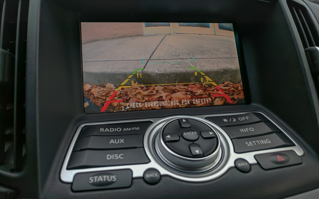
I haven't connected my orange wire yet, so I need to hit the button to bring the camera up.

Registered User
Joined: Mar 2017
Posts: 9
Likes: 0
This is what I was looking for. I have a 2009 G37 without navi and backup camera. To be honest I still do not understand how to connect the wires.
I have few questions and I would be really grateful if you could help.
Do I have to connect the navtool orange wire to reverse and the camera to reverse light as well?
How did you make it wireless?
Did you buy a chrome spoiler with the camera lid or did you mount it some other way?
I was thinking about drilling a hole little off the center and putting a camera there but the grid lines would not be in the right place is there any solution for that?
I would want to connect a wireless display receiver like miracast to mirror my phone screen wireless but have no idea it its going to work.
I found something like this. Maybe I could use it for the camera to connect it wireless?
I have few questions and I would be really grateful if you could help.
Do I have to connect the navtool orange wire to reverse and the camera to reverse light as well?
How did you make it wireless?
Did you buy a chrome spoiler with the camera lid or did you mount it some other way?
I was thinking about drilling a hole little off the center and putting a camera there but the grid lines would not be in the right place
is there any solution for that?I would want to connect a wireless display receiver like miracast to mirror my phone screen wireless but have no idea it its going to work.
I found something like this. Maybe I could use it for the camera to connect it wireless?

Thread Starter
Average Joe
Joined: Sep 2015
Posts: 170
Likes: 51
From: Indiana
I'm here to help!
Do I have to connect the navtool orange wire to reverse and the camera to reverse light as well?
Yes. That way the camera only has power while in reverse, and the Navtool trigger to switch inputs comes on at the same time.
How did you make it wireless?
I used the same modules you found on Amazon. However, I decided to just hardwire it after having some reception issues.
Did you buy a chrome spoiler with the camera lid or did you mount it some other way?
I went with this: CMOS HD Car Reverse Rear View Back up Camera For Infiniti G37 Coupe 2D 2007-2011 | eBay
The camera replaces one of the license plate light covers. You'll still have a light on that side, but the camera is there as well. The distance measurements are off doing it that way, but I don't mind.
Thread Starter
Average Joe
Joined: Sep 2015
Posts: 170
Likes: 51
From: Indiana
Registered User
Joined: Mar 2017
Posts: 9
Likes: 0
I appreciate your help. I did not expect any reply 
Okay so I will do it the way you have. The navtool link you provided does not work anymore, is it the one for $300 with hdmi input?
Oh thats a good option with that camera. So the camera grid lines are not lined up with car/wheels, its a bit on the side?
I want to plug the android tv box permanently but I am not sure how to use it without the touchscreen. Do you have a keyboard or something?
I am also questioning the navigation, does it work with the android box? Do I need any additional gps receiver? I think its more convenient than connecting the phone each time, its mostly going to be used just for navigation.
I am also thinking about adding a touchscreen overlay to the screen. Would it work?
Last edited by M4gnum; Mar 16, 2017 at 03:43 PM.