
DIY: SPC A-arm Installation (Front Camber Adjust)


Thread Starter
Registered User
iTrader: (3)
Joined: May 2006
Posts: 2,929
Likes: 5
From: Sacramento, CA
SPC A-arm Installation (Front Camber Adjust)
Today, I installed my new SPC Front A-arms. If you'd like to purchase a set, hit up Andy at HPAuto. He gave me a great deal, and Andy is an all-around great guy to work with. Thanks Andy @ HPAuto!!
Also, big thanks to Rusty (Extreme G on G35Driver.com) for stopping by to help make short work of the other side!
So let's move on to the installation.
Tools you'll need just for installation:
Field Service Manual (FSM) for torque specs (also provided at end for reference)
(1) jack and jack stand
(1) crescent wrench or channel locks
(1) torque wrench (1/4 and/or 1/2" drive depending on what sockets you have)
(1) socket wrench (again 1/4 and/or 1/2" drive as above)
Assorted sockets:
-10mm for strut tower nuts (3 each side)
-14mm for a-arm bolts (3 each side)
-17mm for sway endlink (1 each side)
-1 1/16" for camber nut on top of spc a-arm (1 each side (I didn't have a 27mm which the instructions call for))
(1) hammer (optional-explained below)
(1) pack of cigarettes and lighter (optional)
(3) cold beverages (optional)
Tools you'll need to check before and after camber:
(1) length of straight-edge the width of your rim
(1) carpenter's level
(1) ruler with millimeter measurement
Excel and attached spreadsheet
Installation:
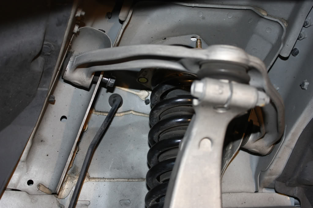
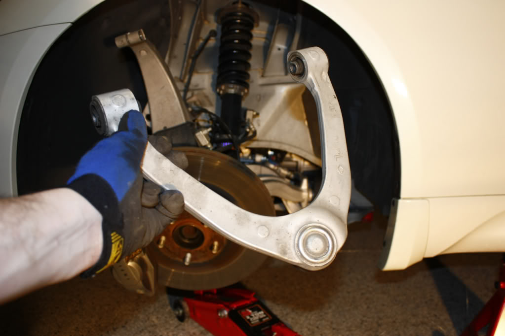
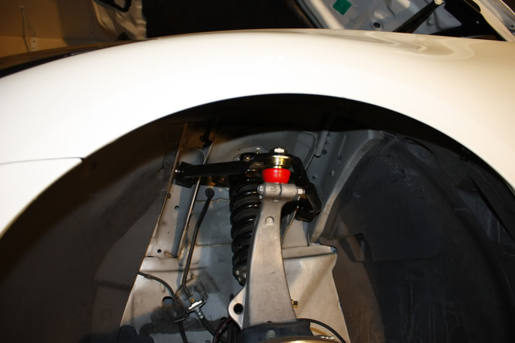
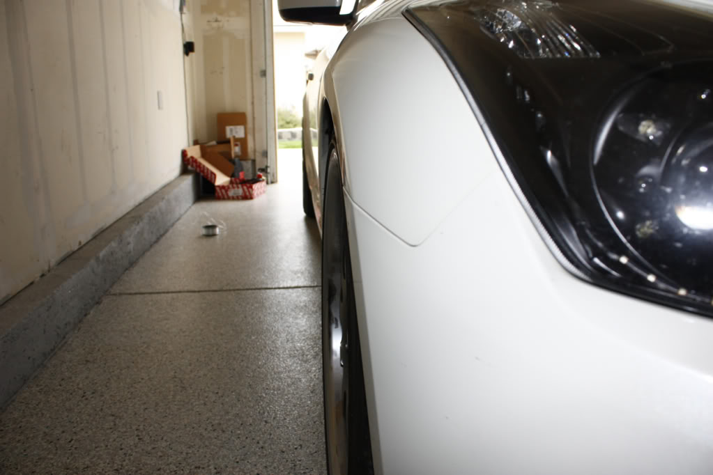
Here is what we're working with. This will be a before picture.
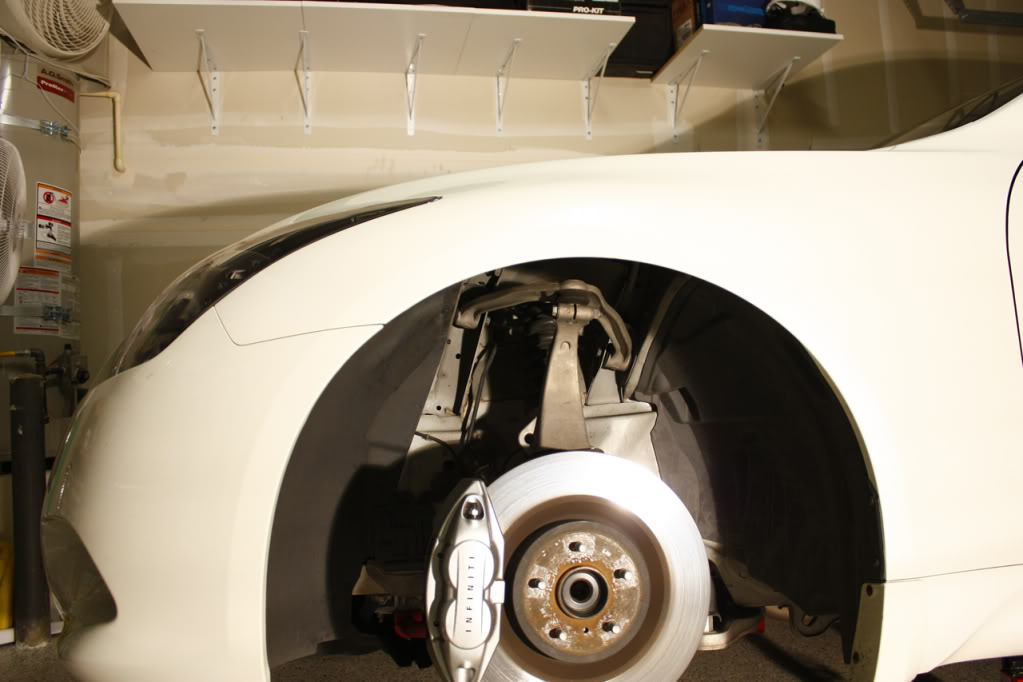
Step 1:
Prep your work area, gather all the tools you'll need, and measure your before camber. Measuring your before camber is fairly simple and will be explained as a supplement at the end of this DIY. Optionally, you can purchase a camber measuring tool, or just use an alignment printout from your latest alignment as reference.
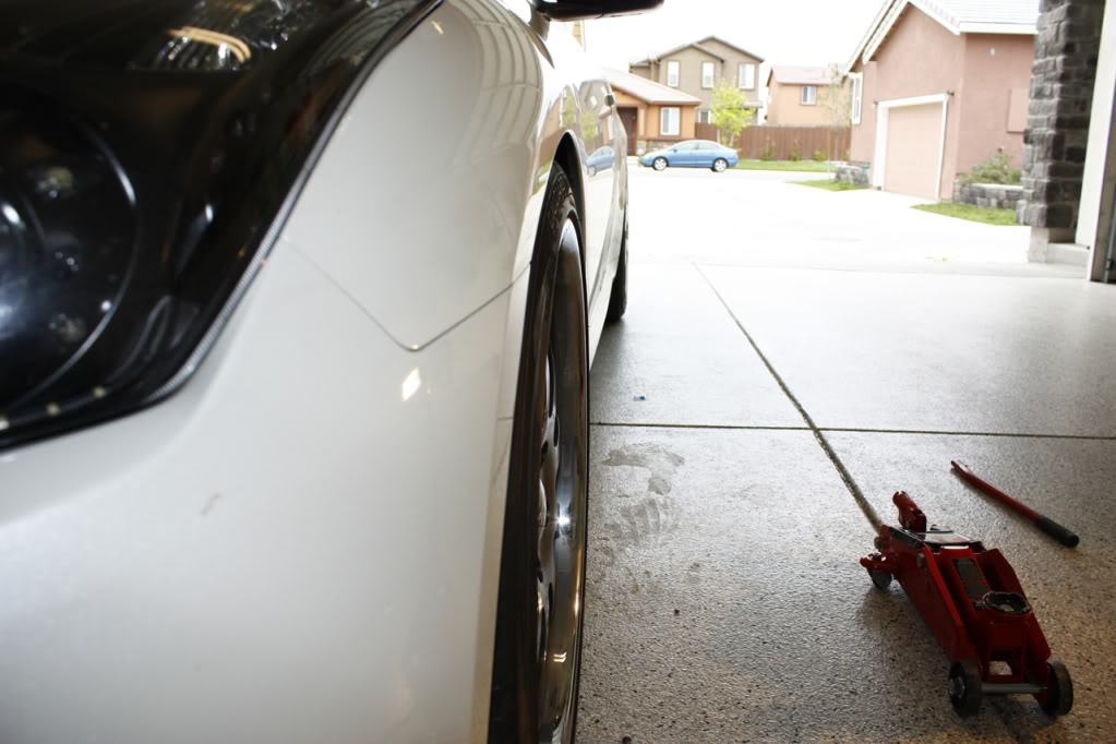
Step 2:
Jack the car up in the front, place a jack stand for support, then remove the jack. Remove (1) front wheel. If you need help with this, you will not be able to handle the rest of this DIY.
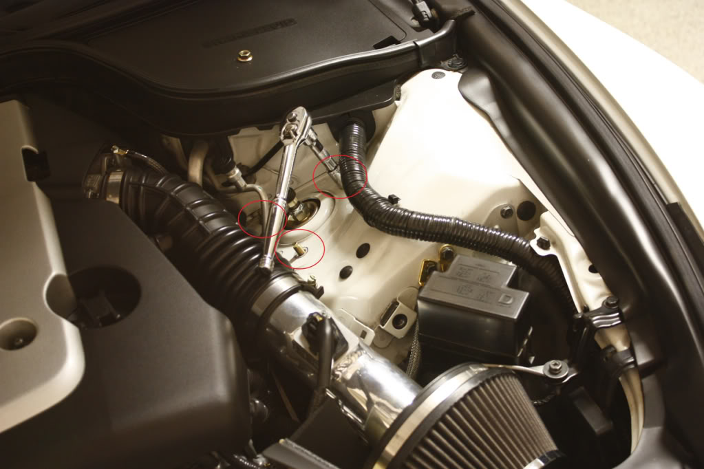
Step 3:
We'll start by removing the (3) strut nuts (10mm) under the hood on the driver's side (the side I was working on for the pics). This step is necessary. the strut will be in the way of the (2) bolts holding the stock/spc a-arm in place.
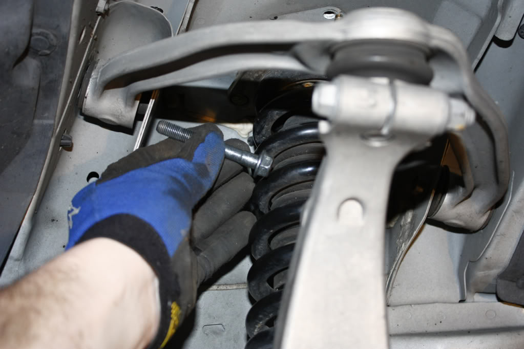
Step 4:
Remove the sway bar endlink bolt (17mm) on the driver's side. You may need to use the crescent wrench/channel locks on the oposite side of the sway as it may spin with the socket. After removing the bolt, the endlink will not slide freely out of the sway bar. We will need this to happen, so now you must place your jack under the bottom of the strut support and slowly jack it up. As you are SLOWLY jackking it up, wiggle the endlink, and it'll eventually slide right out. BE CAREFUL NOT TO JACK UP TOO FAR OR YOU COULD POSSIBLY LIFT THE CAR OFF THE JACK STAND.
Once the endlink bolt is out of the sway bar, SLOWLY drop the jack. Exercise caution here, as the strut will fall out of the (3) mounting holes. This, again, is necessary.
Step 5:
Loosen the left and right (for lack of better terms) bolts (14mm) of the stock a-arm. You will need to reposition the strut as the distance between the strut and the a-arm bolt is shorter than the bolt itself is. Shift the strut over and remove the bolts. Note: There is a bushing on the rearward bolt of the stock a-arm. This will not be needed on the SPC a-arm.
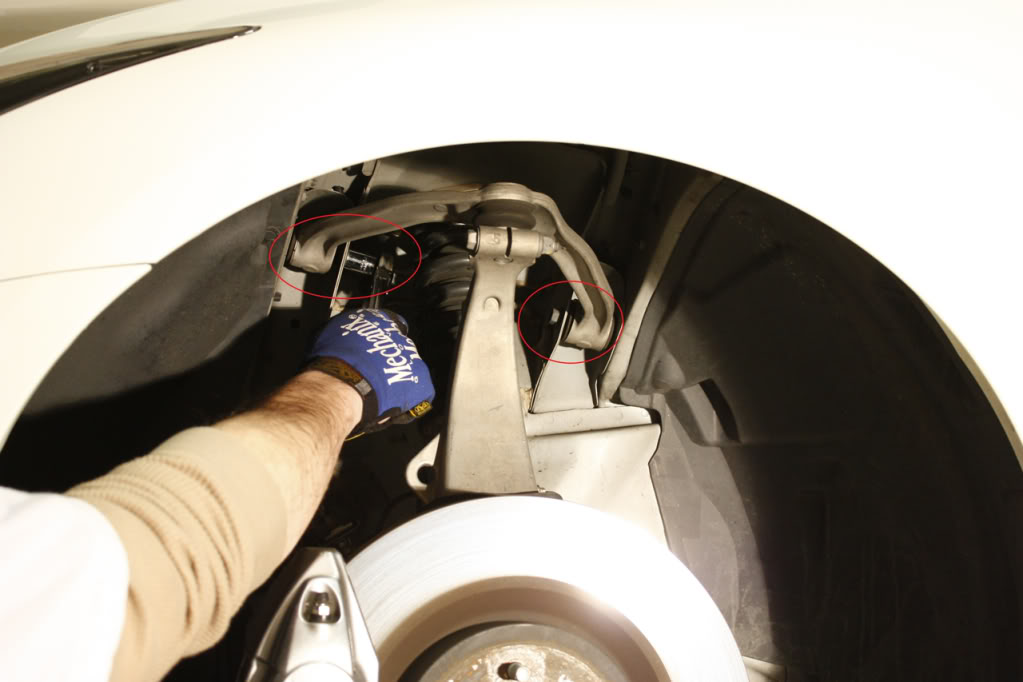
Below, we see the stock a-arm detached from the car. It will come to rest away and forward of the car from tension with the brake line. Be careful here, but I had no problem doing this. Certainly don't put any more pressure on this than there already is.
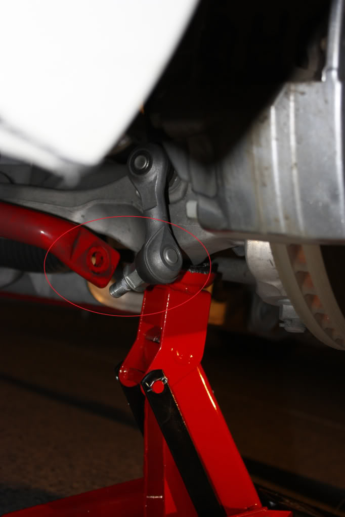
Step 6:
Remove the stock a-arm knuckle bolt (14mm) from the top of the suspension member. You will likely need to use the crescent wrench/channel locks here as the bolt will want to spin.
Once the bolt is removed, slide the stock a-arm knuckle up and out of the suspension member. Voila!!
Step 7:
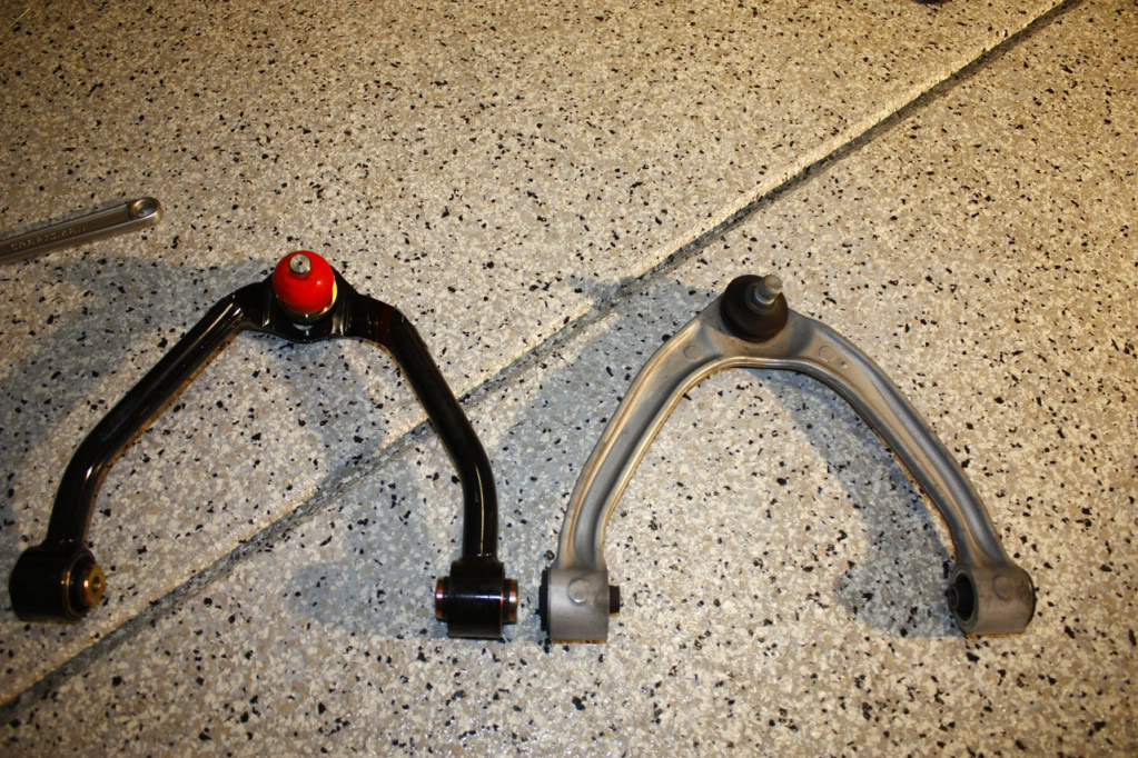
Now we need to adjust the spc a-arm to have either the same or more positve camber than the stock a-arm. First a pic of the two side-by-side.
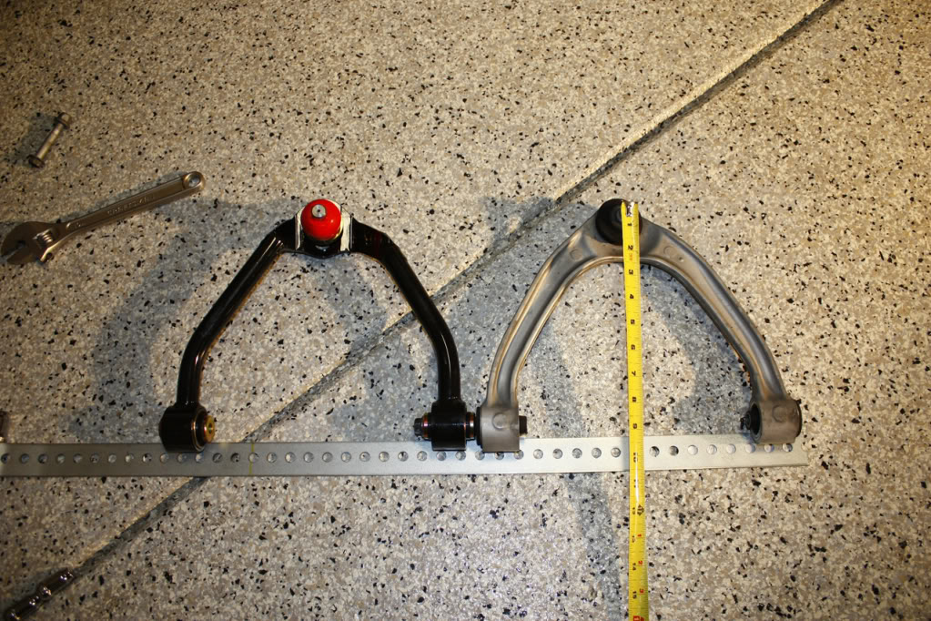
In the next pic, I've place one of the a-arm side bolts into both the spc and stock a-arm, essentially lining up the mounting points. Now, twirl the stock and spc knuckles to try to get them in their middle position. Next, I used a spare piece of straight-edge as a measurement guide and placed it to where it was just touching all four mounting points. From the stock knuckle, use a tape measure to measure the distance to this straight edge. This measurement is not precise but is close enough. Using my spreadsheet, I figured out the distance in millimeters I wanted the spc knuckle to be relative to the stock knuckle. I ended up moving the spc knuckle about 9mm out for better front camber (more positive). Once this is done, tighten the camber nut with the 1-1/16 socket. This will be torqued once on the car.
Step 8:
Now to install the spc a-arm onto the car. First, I started with the knuckle. Slide the knuckle into the top of the suspension member. Here's where the hammer will be useful. Mine was being stubborn, so I gently persuaded it. Once in, lock it in place by replacing the stock bolt and lock nut (14mm).
Per FSM, torque to 41lb-ft.
Step 9:
Slide the spc a-arm into the stock mounting points. Replace the stock left and right bolts (14mm). Again, the strut will need to be pushed asside for clearance.
Per FSM, torque to 52lb-ft.
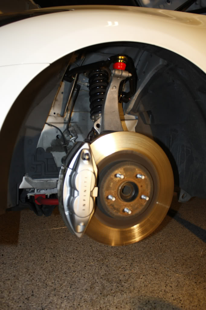
After the above is complete, place your foot on the caliper and press down. You'll need to do this to have access to the top camber nut (27mm or 1-1/16") on the spc a-arm. Once you can place your torque wrench on, torque it down.
Per SPC Instructions, torque to 120lb-ft.
Step 10:
In this step, you'll need to jack the suspension back up SLOWLY and guide the strut mounting bolts back into their mounting holes. After these bolts are through, you'll need to keep jacking (SLOWLY) and slide the sway bar endlink back into the sway bar. Replace strut top nuts (10mm) and sway bar endlink nut (17mm). Again, you may need to use the crescent wrench/channel locks on the endlink.
Per FSM, strut top nuts torque to 28lb-ft
Per FSM, endlink nut torque to 62lb-ft
Step 11 (optional):
While I was down here and dirty, I went ahead and checked tightness on my coilover lock nuts as well as the strut bottom bolt. This bottom bolt is 19mm and is to be torqued to 120lb-ft.
Step 12:
Replace wheel, jack up car at jack point, remove jack stand, drop car.
Rinse and repeat for other side!! Hoorah!!
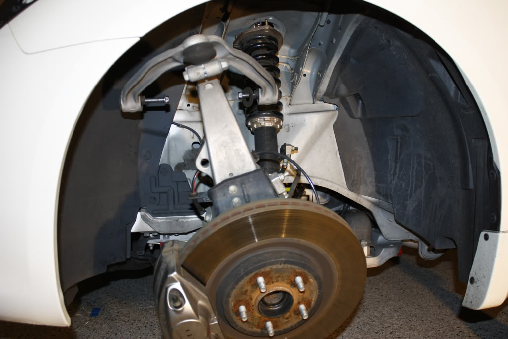
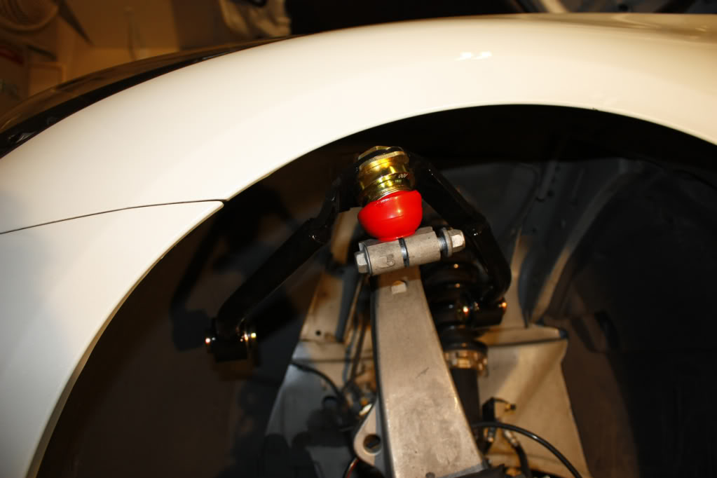
Final pictures of one side done:
OEM from back
SPC from back
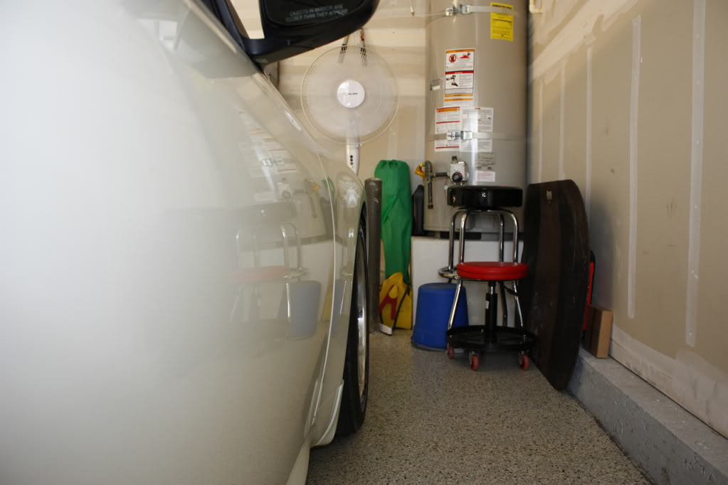
OEM from front
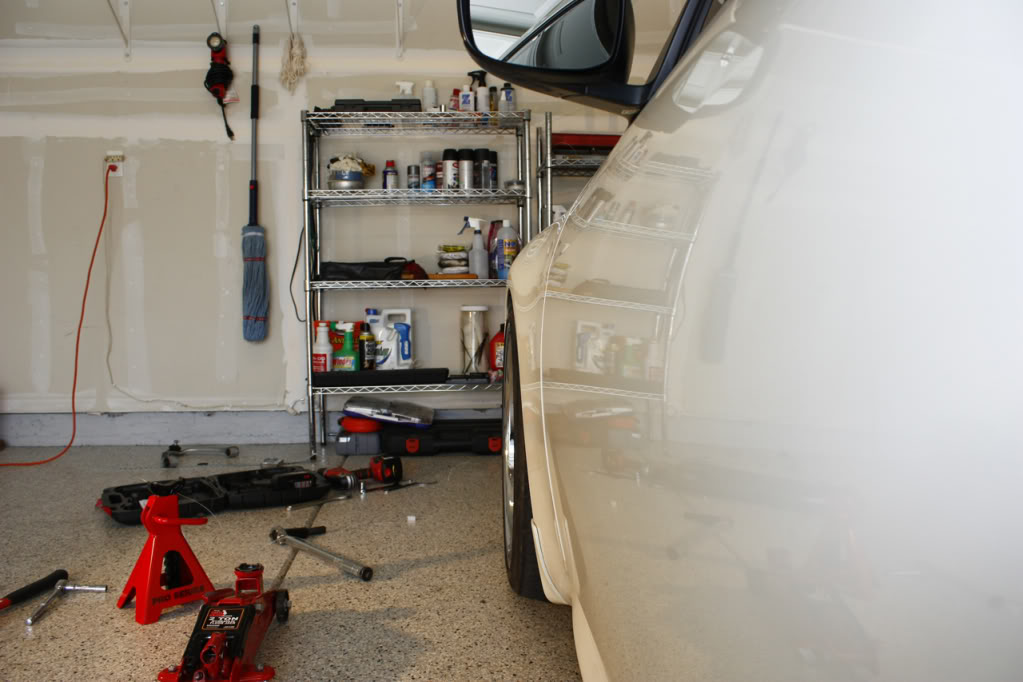
SPC from front
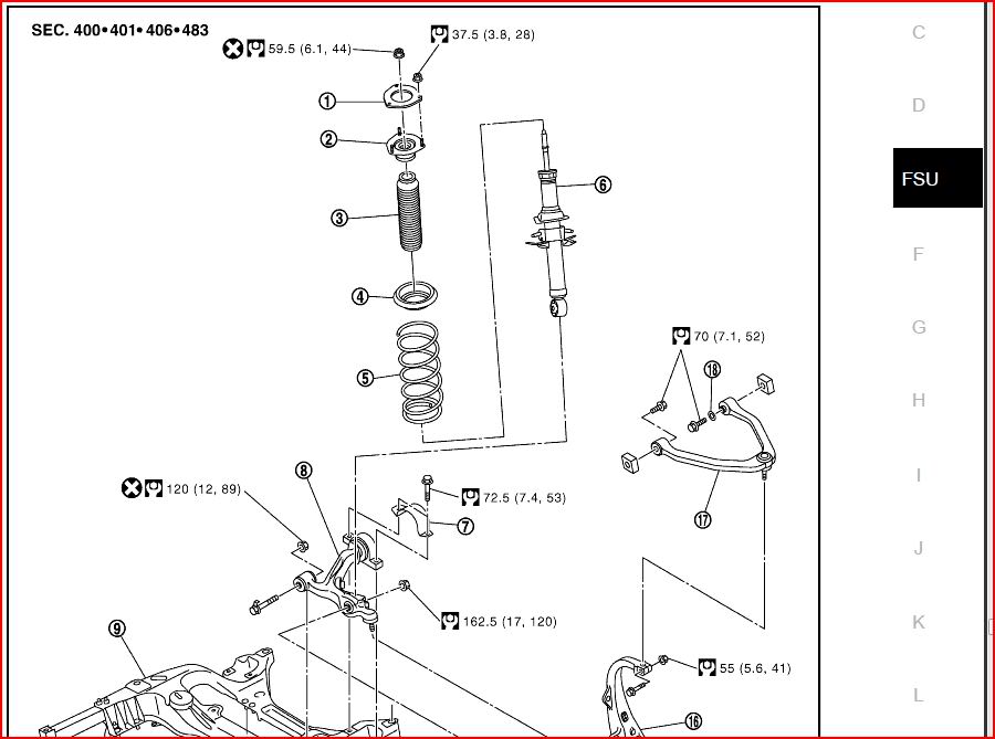
Supplemental: FSM front suspension exploded view
Here is a snapshot for torque verifications.
Supplemental Camber info:
I've done a good deal of research into DIY alignment, and found a GREAT youtube video of it. I'll provide the link to (2) videos. In the first vid at approx 3:22, you'll see the method used to measure the camber in a millimeter distance. In the second vid at approx 1:07, he goes into how to convert this measurement into degrees. I've attached a spreadsheet which will calculate your camber angle for you. All you have to do is input the length of the straight-edge used and the distance to plumb (in (-)mm).
This DIY is NOT intended to cover alignment, but this is helpful for getting your front camber to a more positive position after lowering. The full (3) videos from this guy are great and full of very good info on DIY alignment.
For reference, my starting camber was -1.9deg, and ending camber is -0.9deg. It CAN go further positive. I'll adjust it further in a couple of weeks.
DOMO
Also, big thanks to Rusty (Extreme G on G35Driver.com) for stopping by to help make short work of the other side!
So let's move on to the installation.
Tools you'll need just for installation:
Field Service Manual (FSM) for torque specs (also provided at end for reference)
(1) jack and jack stand
(1) crescent wrench or channel locks
(1) torque wrench (1/4 and/or 1/2" drive depending on what sockets you have)
(1) socket wrench (again 1/4 and/or 1/2" drive as above)
Assorted sockets:
-10mm for strut tower nuts (3 each side)
-14mm for a-arm bolts (3 each side)
-17mm for sway endlink (1 each side)
-1 1/16" for camber nut on top of spc a-arm (1 each side (I didn't have a 27mm which the instructions call for))
(1) hammer (optional-explained below)
(1) pack of cigarettes and lighter (optional)
(3) cold beverages (optional)
Tools you'll need to check before and after camber:
(1) length of straight-edge the width of your rim
(1) carpenter's level
(1) ruler with millimeter measurement
Excel and attached spreadsheet
Installation:
Here is what we're working with. This will be a before picture.
Step 1:
Prep your work area, gather all the tools you'll need, and measure your before camber. Measuring your before camber is fairly simple and will be explained as a supplement at the end of this DIY. Optionally, you can purchase a camber measuring tool, or just use an alignment printout from your latest alignment as reference.
Step 2:
Jack the car up in the front, place a jack stand for support, then remove the jack. Remove (1) front wheel. If you need help with this, you will not be able to handle the rest of this DIY.
Step 3:
We'll start by removing the (3) strut nuts (10mm) under the hood on the driver's side (the side I was working on for the pics). This step is necessary. the strut will be in the way of the (2) bolts holding the stock/spc a-arm in place.
Step 4:
Remove the sway bar endlink bolt (17mm) on the driver's side. You may need to use the crescent wrench/channel locks on the oposite side of the sway as it may spin with the socket. After removing the bolt, the endlink will not slide freely out of the sway bar. We will need this to happen, so now you must place your jack under the bottom of the strut support and slowly jack it up. As you are SLOWLY jackking it up, wiggle the endlink, and it'll eventually slide right out. BE CAREFUL NOT TO JACK UP TOO FAR OR YOU COULD POSSIBLY LIFT THE CAR OFF THE JACK STAND.
Once the endlink bolt is out of the sway bar, SLOWLY drop the jack. Exercise caution here, as the strut will fall out of the (3) mounting holes. This, again, is necessary.
Step 5:
Loosen the left and right (for lack of better terms) bolts (14mm) of the stock a-arm. You will need to reposition the strut as the distance between the strut and the a-arm bolt is shorter than the bolt itself is. Shift the strut over and remove the bolts. Note: There is a bushing on the rearward bolt of the stock a-arm. This will not be needed on the SPC a-arm.
Below, we see the stock a-arm detached from the car. It will come to rest away and forward of the car from tension with the brake line. Be careful here, but I had no problem doing this. Certainly don't put any more pressure on this than there already is.
Step 6:
Remove the stock a-arm knuckle bolt (14mm) from the top of the suspension member. You will likely need to use the crescent wrench/channel locks here as the bolt will want to spin.
Once the bolt is removed, slide the stock a-arm knuckle up and out of the suspension member. Voila!!
Step 7:
Now we need to adjust the spc a-arm to have either the same or more positve camber than the stock a-arm. First a pic of the two side-by-side.
In the next pic, I've place one of the a-arm side bolts into both the spc and stock a-arm, essentially lining up the mounting points. Now, twirl the stock and spc knuckles to try to get them in their middle position. Next, I used a spare piece of straight-edge as a measurement guide and placed it to where it was just touching all four mounting points. From the stock knuckle, use a tape measure to measure the distance to this straight edge. This measurement is not precise but is close enough. Using my spreadsheet, I figured out the distance in millimeters I wanted the spc knuckle to be relative to the stock knuckle. I ended up moving the spc knuckle about 9mm out for better front camber (more positive). Once this is done, tighten the camber nut with the 1-1/16 socket. This will be torqued once on the car.
Step 8:
Now to install the spc a-arm onto the car. First, I started with the knuckle. Slide the knuckle into the top of the suspension member. Here's where the hammer will be useful. Mine was being stubborn, so I gently persuaded it. Once in, lock it in place by replacing the stock bolt and lock nut (14mm).
Per FSM, torque to 41lb-ft.
Step 9:
Slide the spc a-arm into the stock mounting points. Replace the stock left and right bolts (14mm). Again, the strut will need to be pushed asside for clearance.
Per FSM, torque to 52lb-ft.
After the above is complete, place your foot on the caliper and press down. You'll need to do this to have access to the top camber nut (27mm or 1-1/16") on the spc a-arm. Once you can place your torque wrench on, torque it down.
Per SPC Instructions, torque to 120lb-ft.
Step 10:
In this step, you'll need to jack the suspension back up SLOWLY and guide the strut mounting bolts back into their mounting holes. After these bolts are through, you'll need to keep jacking (SLOWLY) and slide the sway bar endlink back into the sway bar. Replace strut top nuts (10mm) and sway bar endlink nut (17mm). Again, you may need to use the crescent wrench/channel locks on the endlink.
Per FSM, strut top nuts torque to 28lb-ft
Per FSM, endlink nut torque to 62lb-ft
Step 11 (optional):
While I was down here and dirty, I went ahead and checked tightness on my coilover lock nuts as well as the strut bottom bolt. This bottom bolt is 19mm and is to be torqued to 120lb-ft.
Step 12:
Replace wheel, jack up car at jack point, remove jack stand, drop car.
Rinse and repeat for other side!! Hoorah!!
Final pictures of one side done:
OEM from back
SPC from back
OEM from front
SPC from front
Supplemental: FSM front suspension exploded view
Here is a snapshot for torque verifications.
Supplemental Camber info:
I've done a good deal of research into DIY alignment, and found a GREAT youtube video of it. I'll provide the link to (2) videos. In the first vid at approx 3:22, you'll see the method used to measure the camber in a millimeter distance. In the second vid at approx 1:07, he goes into how to convert this measurement into degrees. I've attached a spreadsheet which will calculate your camber angle for you. All you have to do is input the length of the straight-edge used and the distance to plumb (in (-)mm).
This DIY is NOT intended to cover alignment, but this is helpful for getting your front camber to a more positive position after lowering. The full (3) videos from this guy are great and full of very good info on DIY alignment.
For reference, my starting camber was -1.9deg, and ending camber is -0.9deg. It CAN go further positive. I'll adjust it further in a couple of weeks.
DOMO
Last edited by finagle69; May 12, 2009 at 11:32 AM. Reason: Torque spec corrections - Thx HamstersG


 hope it helps some people out.
Trending Topics

Registered User
Joined: Sep 2005
Posts: 120
Likes: 4
From: NE Ohio
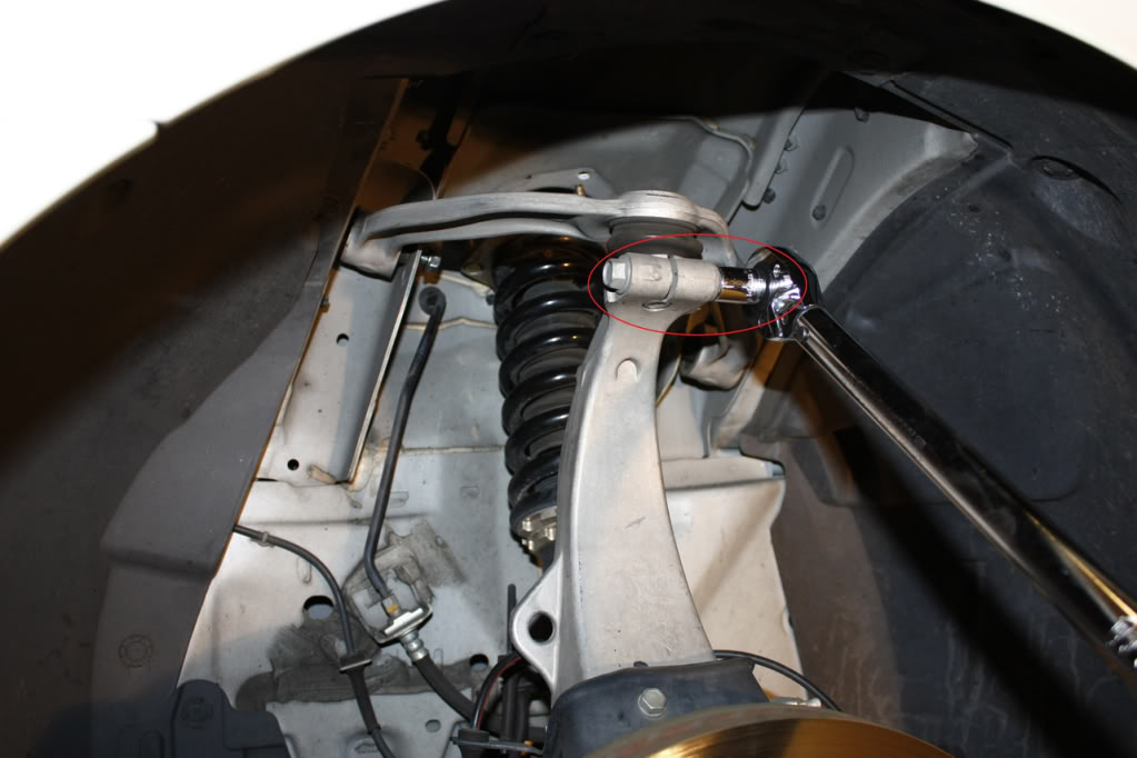
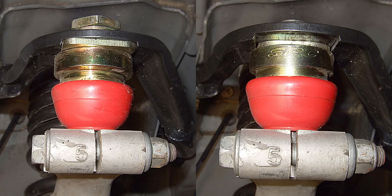
Not sure what the adjustment range is on the coupe but for the sedan (what I have), even with Eibach springs (ie. conservative drop), it is better to have the ball joint position "outward" with the SPC logo facing outward (right side of pic below)--you get more positive camber correction that way. It is easy to reverse the ball joint 180* by removing the top locking nut, but it may be simpler just to do so before you take it in for alignment, rather than to let your shop figure it out. Just jack up each side at a time--there is plenty of room to do it without removing your wheel.
I am not sure why the camber arms come with ball joint "inward" but if you look at the instructions, it seems to indicate that ball joint "outward" is default. Makes sense that SPC would put their logo on the outside as well.
I am not sure why the camber arms come with ball joint "inward" but if you look at the instructions, it seems to indicate that ball joint "outward" is default. Makes sense that SPC would put their logo on the outside as well.
Thread Starter
Registered User
iTrader: (3)
Joined: May 2006
Posts: 2,929
Likes: 5
From: Sacramento, CA
Not sure what the adjustment range is on the coupe but for the sedan (what I have), even with Eibach springs (ie. conservative drop), it is better to have the ball joint position "outward" with the SPC logo facing outward (right side of pic below)--you get more positive camber correction that way. It is easy to reverse the ball joint 180* by removing the top locking nut, but it may be simpler just to do so before you take it in for alignment, rather than to let your shop figure it out. Just jack up each side at a time--there is plenty of room to do it without removing your wheel.
I am not sure why the camber arms come with ball joint "inward" but if you look at the instructions, it seems to indicate that ball joint "outward" is default. Makes sense that SPC would put their logo on the outside as well.
I am not sure why the camber arms come with ball joint "inward" but if you look at the instructions, it seems to indicate that ball joint "outward" is default. Makes sense that SPC would put their logo on the outside as well.
I also noticed that, after installation, my fronts were about 1/4" higher due to the additional material there. I'll be lowering my front this evening and will probably need the additional positive camber adjustment by flipping it around.

Registered User
Joined: Sep 2005
Posts: 120
Likes: 4
From: NE Ohio
If you mean that the car sits higher--that really shouldn't change.
I also noticed this after I installed my arms but thankfully, flipping the ball joints around took all of 15 minutes. I did have to go out an buy a 27mm wrench because there is not enough room to fit a socket on there. One of the test fitters for the 07-08 sedan A-arms published results of his alignment tests he did for SPC and got a range of (-3.9 to -0.7) with the ball on the inside position and a range of (-2 to +1.2) with the outside position--he had Eibach springs.
I also noticed this after I installed my arms but thankfully, flipping the ball joints around took all of 15 minutes. I did have to go out an buy a 27mm wrench because there is not enough room to fit a socket on there. One of the test fitters for the 07-08 sedan A-arms published results of his alignment tests he did for SPC and got a range of (-3.9 to -0.7) with the ball on the inside position and a range of (-2 to +1.2) with the outside position--he had Eibach springs.

Thread Starter
Registered User
iTrader: (3)
Joined: May 2006
Posts: 2,929
Likes: 5
From: Sacramento, CA

Registered User
Joined: Mar 2009
Posts: 86
Likes: 0
From: Orlando, Fl
Great DIY! Thanks. I ordered a set of Eibach Pro Kit Springs and SPC front & rear camber kits from Andy at HPAuto last week as well. He gave me a really good deal too. I can't wait until they get here. Your car looks great. You're DIY made the install look a lot easier then I thought it was going to be.