When you click on links to various merchants on this site and make a purchase, this can result in this site earning a commission. Affiliate programs and affiliations include, but are not limited to, the eBay Partner Network.
How I replaced & upgraded the center display with high-res Andriod Auto for $220
This project is a total screen replacement and should work on ALL 2007-2009, and 2010+ NON Tech. Tech will not be able to display the stock UI on the new screen I am not responsible if you mess your car up performing this mod!
To install, flash Raspbian onto an SD card and load onto your Pi. Follow the dash install instructions on the wiki. (Will attach my install doc to this post)
Note that after you flash the image, you need to change the config so the display will show up properly on a 7" display. Put the following at the bottom of config.txt on the root of the SD card.
Wiring and hardware modifications:
All of the new components will be powered via the connector the stock board plugs into.
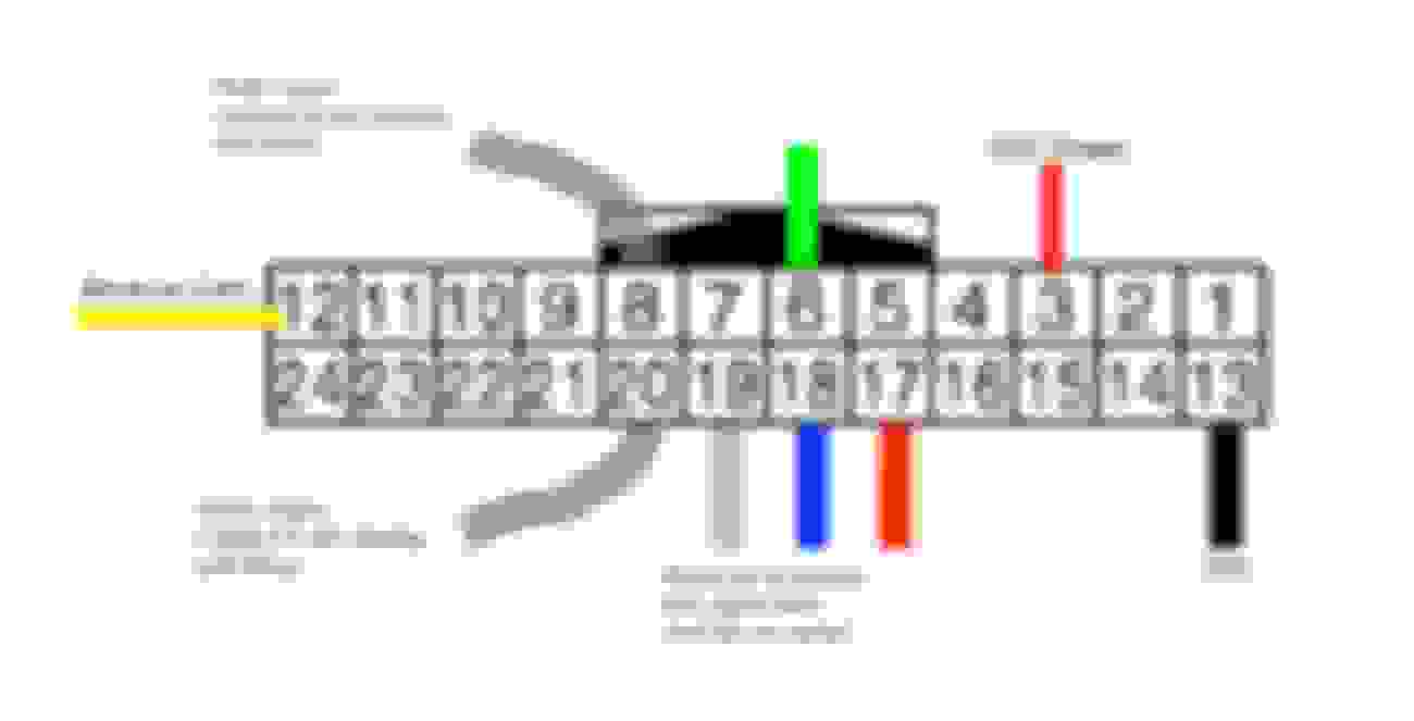
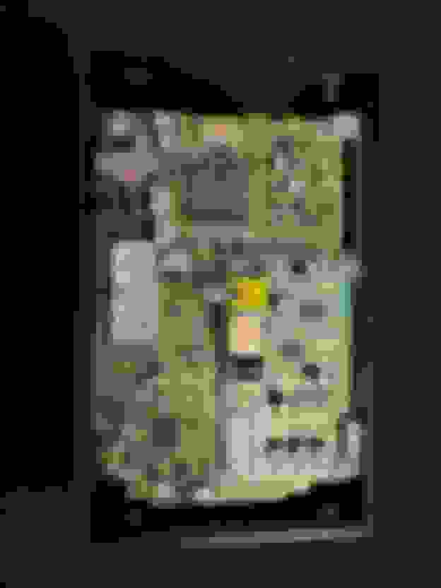
First you�ll need to modify your stock board by soldering onto the required pins on the back of the unit. You need to keep the stock board in the system or you won�t get any video
Next you�ll need to identify the pins required for power, video, backup cam (if equipped).
Important � CHECK THESE PINS FOR YOUR YEAR, IT MAY HAVE CHANGED.
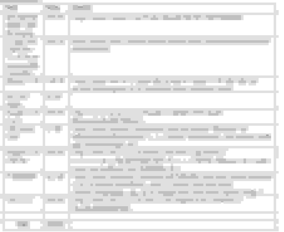
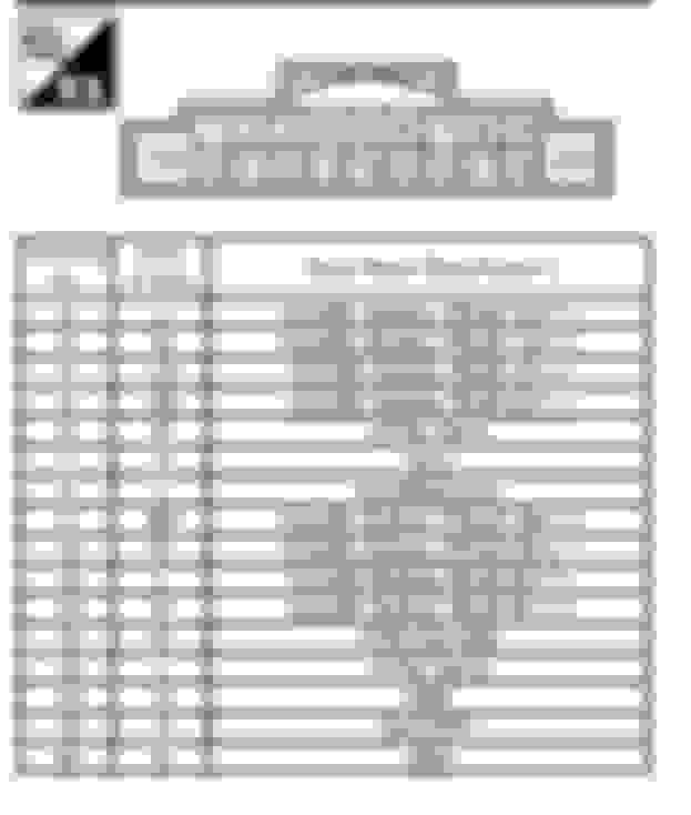
G35 2008 Nav / Bose / Tech
Spoiler
Pins on display unit connector:
3 - ACC Power � To Weiya CV-04 and LCD Driver Board (J3 power input)
6 � GREEN � To Weiya CV-04
8 - Horizontal Sync - To Weiya CV-04
12 - Reverse Camera � To AV2 on LCD Driver board (J5 connector)
13 � Ground � To Weiya CV-04 and LCD Driver board (J3 power input)
17 � RED - To Weiya CV-04
18 � BLUE - To Weiya CV-04
20 - Vertical Sync - To Weiya CV-04
On AV Unit Connector:
37 � Reverse Signal � To ACC pin on LCD Driver Board. (J5 connector)
From Weiya CV-04 to LCD board:
Composite out needs to go to AV1 pins on LCD board. (J5 connector)
At this point, the wiring is complete. You can plug it into the car now and make sure it boots up. If you did it correctly the inputs should work as followed:
AV1 � Stock Infiniti Interface
AV2 � Backup Camera
HDMI � Pi Note � You may have to flash the board
When you shift into reverse, the screen should automatically switch to AV2 and show the backup camera. Switch back to drive and it�ll go back to whatever input you were on before.
Next you�ll need to fit everything into one unit which can be installed back behind the dash. I�ve designed a housing to hold all these components, and mount up just like stock.
After mounting the new housing back into the frame you�ll want to also run the wires for the HDMI and USB digitizer to the Pi, as well as the wires for the LCD board remote. I ran the HDMI and digitizer wires under the passenger seat. The LCD board remote is run into the center �not an ashtray.�
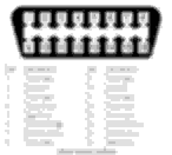
You�ll also need to run wires from your OBD port into the CAN HAT, in order to make the G37 plugin function properly. You need Can High (pin6), Can Low (pin14), and ground(pin4), which go to the corresponding terminals on the Raspberry Pi�s CAN hat.
After this, just reinstall everything back and it�s all done! Enjoy your new updated center display. Really makes the car feel modern again.
OPTIONAL:Flashing the Display Board with OpenRTD (RTD2662)
There is an alternative firmware for the display board I�m using, called OpenRTD. This firmware adds a number of improvements, such as no ugly blue startup screen, no OSD popups on switching, faster reverse camera switching (and the ability to pick which AV input is used for switching)
Parts Needed:
Teensy LC
500Ohm Resistor
Wiring:
Teensy ground to chassis ground � I used a crimp on spade and placed it under a screw.
500ohm resistor between 3.3v and pin A9 > to harness pin 6 on this connector behind the AV unit. (pin 6 needs to be disconnected from the AV unit)
Flash the attached sketch onto the Teensy, test, and then plug the teensy into the Pi. Wheel controls should now work automatically.
Final Product:
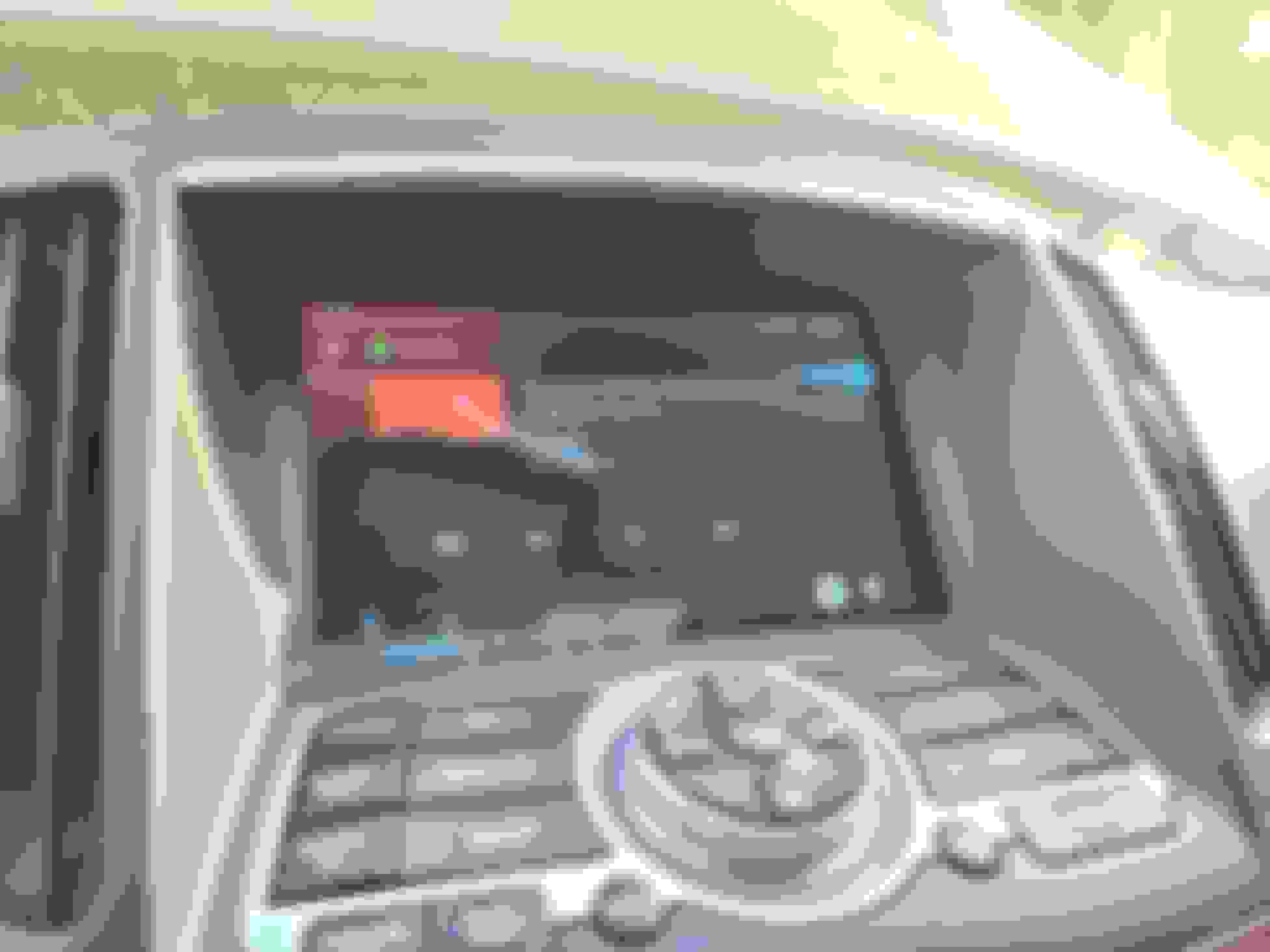
Stock UI:
Reverse:
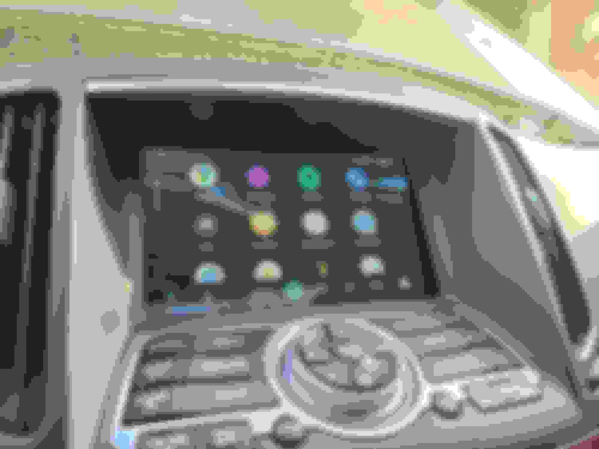
Android Auto
Spotify
Final Thoughts:
I�ve been using this setup for a little over a year now and I�m very happy with it. The replacement screen is much higher resolution � and is LED backlit rather than CCFL backlit so the colors are better as well. Makes the car a lot more modern feeling.
Cons:
stock UI will be slightly degraded quality due to the signal conversion and being upscaled onto the higher res display. That said, it�s still totally usable and readable.
Improvements:
Figure out auto screen dimming.
Last edited by iCrap; 07-07-2021 at 01:24 PM.
Reason: Updated Info.
This is amazing! Great job. If your ever lookin to do another one I would be interested. I'm located in MD so maybe we could link up if your interested of course.
This is amazing! Great job. If your ever lookin to do another one I would be interested. I'm located in MD so maybe we could link up if your interested of course.
Before I do any more I want to finalize my harness and 3D Printed housing since it will make this project a lot easier. But yeah I will post info about all that once it's complete.
....wow looks good and functions well....very nice !
.......ever consider making/pre assembling these and selling ?
I'm working on it. I am currently making two harnesses and I have one guy already who is going to test it for me. I'm going to build my own second prototype version soon as well.
Yeah, I believe the camera controller is a separate unit somewhere in the trunk right? I didn't know they changed that after 2010. That would have to be looked at for doing this mod on a 2010+ then.
I discovered that recently. I put a backup camera from a similar year Rogue in my car (fisheye lens) and the colors are off so I eventually found a rogue camera controller. Come to find out, 2010+ integrated that into the a/v controller.
still have the rogue camera control - wiring wise it is much like the 2009 g37 as you would imagine.
wonder if you could just set things up so that the reverse switch causes the pi to show the OEM display - it�s already showing the backup cam at that time. And one less signal for you to integrate.
Oh - no that doesn't work. If you show the OEM display while in reverse you will only see the "LOOK BEFORE BACKING" text or whatever it says. So on the OEM setup it's actually overlaying that over the other input when you go into reverse.
But, if for some reason the 2010 one does it different you can easily set it up to just switch back to OEM display during reverse. The ACC signal to reverse just changes to AV2, so just do AV2-OEM Display and don't use AV1 at all.
Clearly I need to get a 2010+ to run on the bench.
Right now bluetooth into the OEM unit, BUT I am going to change it so it goes through the Pi instead. Reason being so that I can use the apps on OpenAuto and have sound working.
 05-17-2020, 01:11 AM


 ....wow looks good and functions well....very nice !