When you click on links to various merchants on this site and make a purchase, this can result in this site earning a commission. Affiliate programs and affiliations include, but are not limited to, the eBay Partner Network.
When I purchased my car, I noticed the clock did not light up. I read thread after thread of others having the same issue. Most just got a new clock under warranty. There is very little info out there on possible fixes. Well, last night, I decided to try my hand at solving this problem.
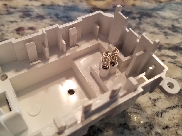
Inside the clock, there are 4 springs that connect the pins from the plug to 4 pads on the circuit board. I read that the springs may have become compressed not allowing contact so the lights do not illuminate. Took the clock apart and the springs appeared to have a good connection. Bummer.
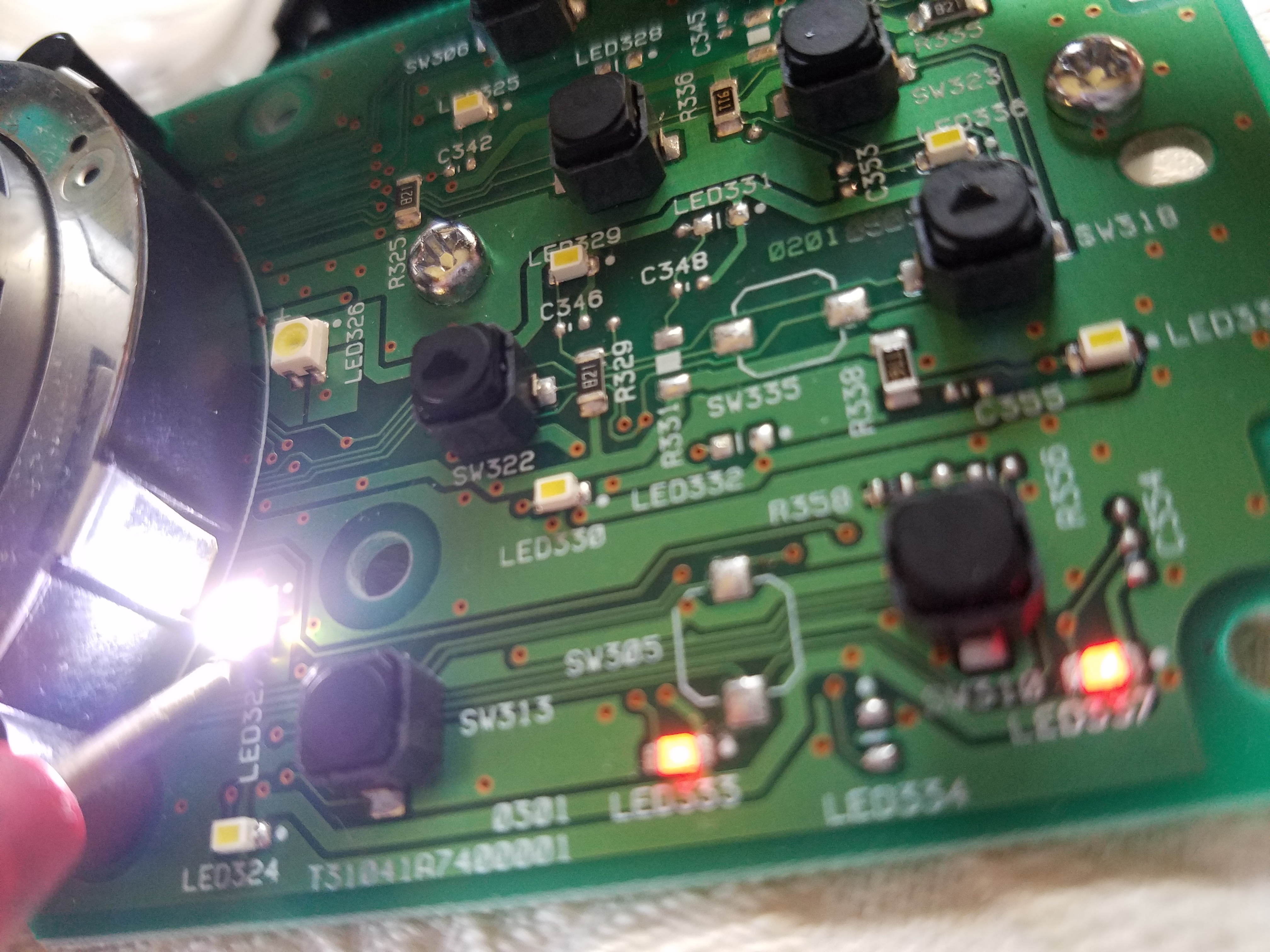
Thankfully the 4 pads on the board are labeled so I knew which ones were + and – for the illumination. I then figured out which pads corresponds with the pins in the connector and then to the harness in the car. Tested to make sure I was getting voltage. I was, and the voltage dropped when dimming the dash. So far so good.
Next, tested the LEDs (before removing them from the board) and the LEDs were indeed bad . Not the end of the world, I will just replace them.
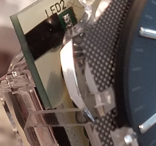
Removed the LEDs and using a multimeter tried to figure out which LED contacts (on the board) were + and which were -, I did not simply want to rely on the cathode mark on the LED. Long story short (I will not bore you will all the details I learned), it seems that neither the + nor - pads where power is supplied on the board are connected to the pads where the LEDs are soldered on…. at all.
This was a real downer, it seems that the circuit board is bad… at least for the illumination.
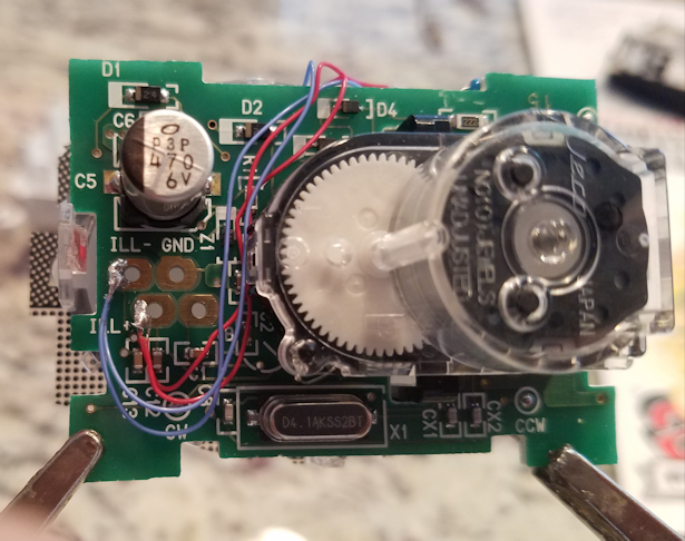
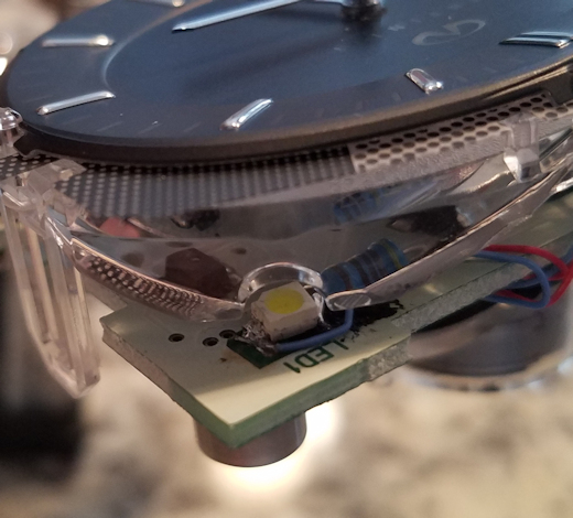
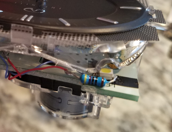
So here is what I did….. I first covered the + pads where the LEDs go with electrical tape (I did not want to re-introduce power to the board) and soldered the - side of the LEDs to the board. Added a resistor to the + side and simply ran wires from the LEDs to the pads where the springs connect. (Go ahead, make fun of my solder joints.... this stuff is TINY! lol)
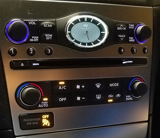
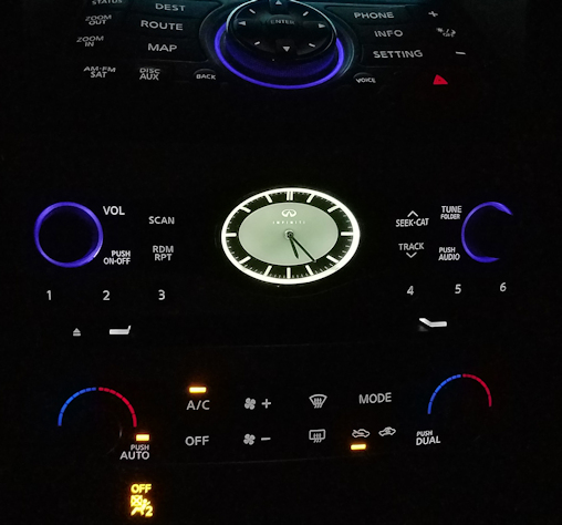
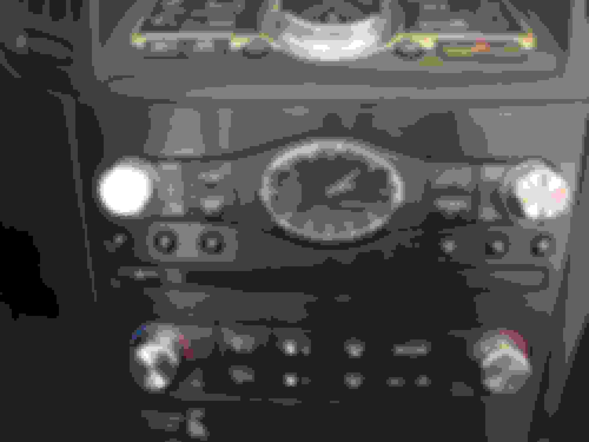
Now my clock lights (and dims)!!!
It's little too bright. I may replace the resistors with a higher ohm version to get the brightness closer to the rest of the dash. I wish I knew the wavelength of the blue/purple OEM LEDs. My guess would be low 400s. I may just get this to scavenge the lights! 10-15 INFINITI EX35 G37 QX50 AUDIO INFORMATION CONTROL PANEL UNIT CC4774 | eBay
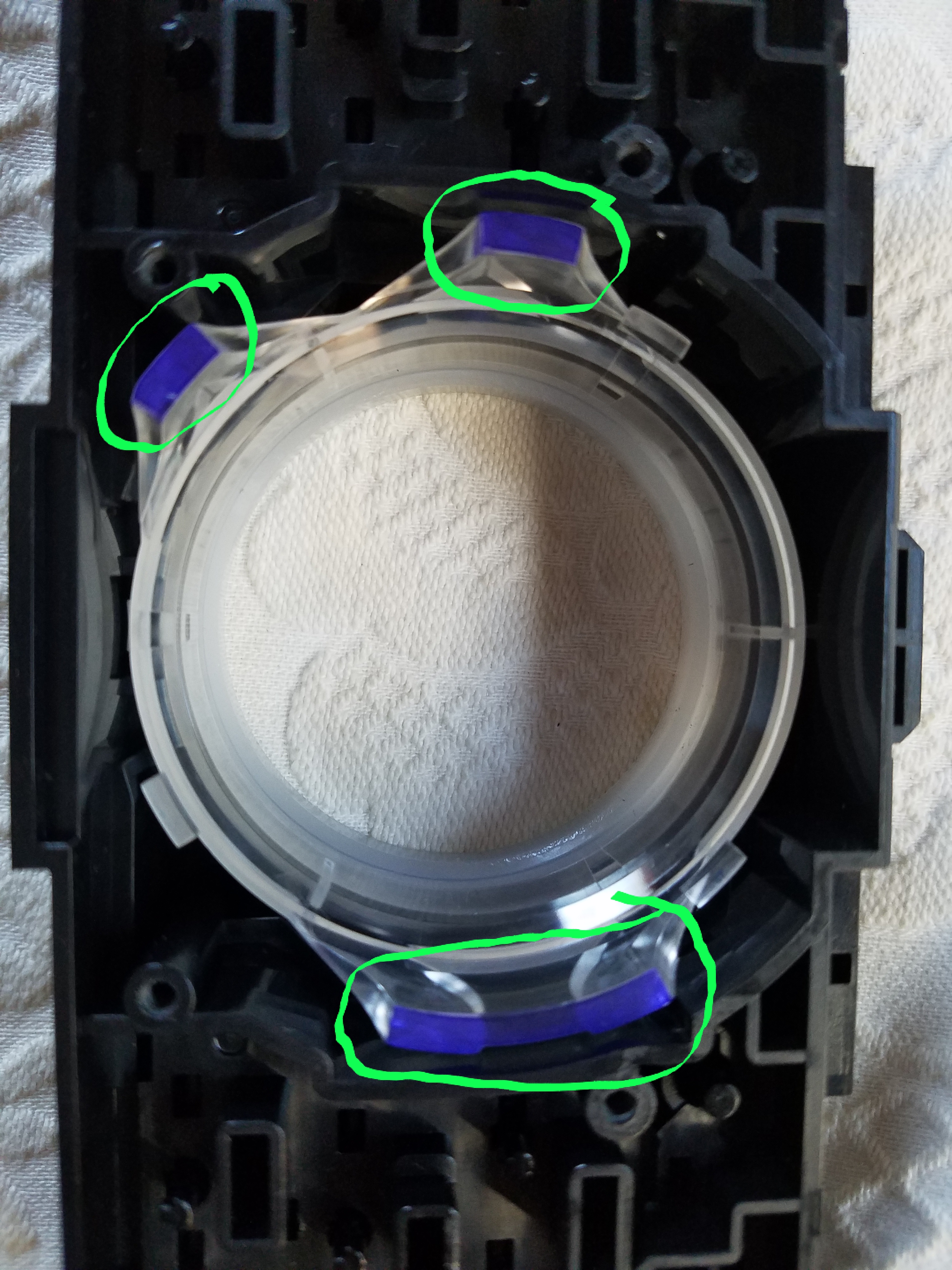
Nice writeup on the clock repair. Scavenging the LED's from the MFD assembly (eBay) will not work. There are 4 superbright LED's that light up the dial. There is a blueish/purplish dye on the illumination lens that, when lit, give off the color.
I had the same idea when I went to modify my start button. I had a extra switch assembly from my NAV swap and gave it a shot. No go.
I think it is safe to assume that the two radio dials are the same way as they both have a similar lens around the dial.
As far as I can tell the LED's for the clock are white. I do not know if the clock face has a color filter built-in or not. As for the NAV and radio dials, I tried to figure something out but in the end did not see how the filters can be modified to work on the start button and thus probably the same for the clock.
I have been meaning to do something similar. Just need to find the time. My LED's aren't bad. I know this because every once in a while they will flicker.
So I attempted this fix today. I used to be good at soldering but that was when I could see.
I removed the surface mounted LED's then proceeded to destroy them while trying to solder new leads onto them.
That's when I went on to plan B.
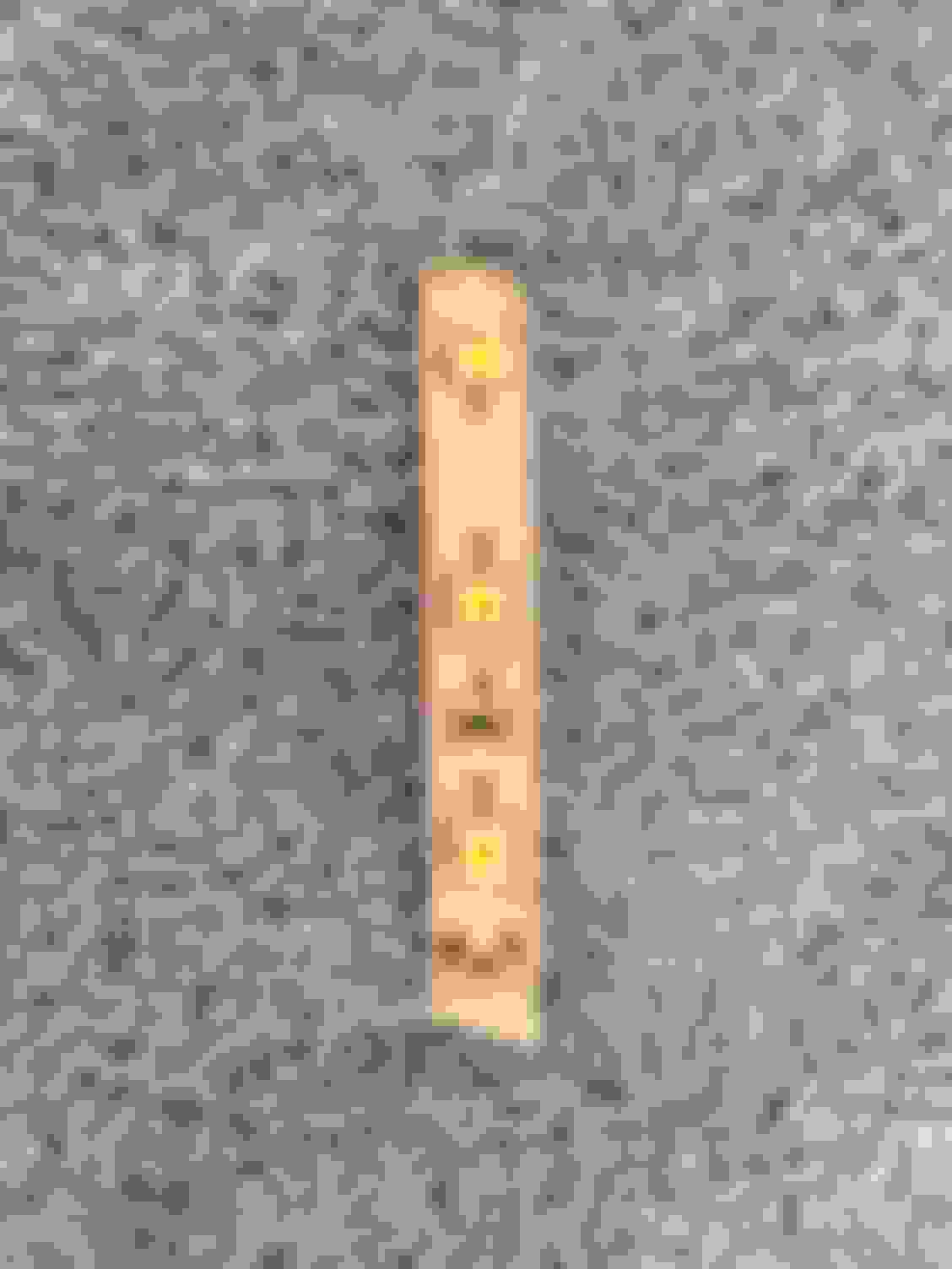
I was rummaging through my tool bench when I remembered that I had some strip LED's left over from installing my kitchen cabinet lighting. These are 12V and have resistors already in line.
I cut a strip just long enough to fit in the clock and taped over the middle LED. The outer ones were almost in perfect position.
I soldered wires on the end and ran the new wire thru a hole I drilled in the back of the clock.
I attached those wires directly to the illumination wires in the harness.
Initially it was too bright even at the lowest brightness
So I added a 1000 ohm resistor and it's at a good level now but unfortunately it doesn't dim any more. Must have something to do with the added resistor.
I'll have to see how it looks at night. Still some room for improvement but seeing as this was a $0 fix it'll work for now.
If only the gauge cluster LED's were as easy. Mine flickers worse than a damn Christmas tree. I can not solder for crap- patience I do not have at all.
The only thing I would have done different with your setup is I would have kept the wires in the clock, but your way works too. Good gob!
The color is a by product of what I had laying around. I may still change it up and get different LED's.
I brought the wires out of the clock so that I could change things down the road if necessary. I just tapped into the harness so it's not chopped at all.
Added a resistor to the + side and simply ran wires from the LEDs to the pads where the springs connect.
Entcee, thanks for the great write up and pictures, I will definitely be tackling this tomorrow on one of the two clocks I have. Can you tell me what size resistor you used?
It really depends on the specs of the LED. Most white surface mount LEDs run around 3.2v and around 25mA. Using Ohm's law (R=V/I) R=(14.4v-3.2v)/.025. This gave a resistance value of 448. So you would need a 470 ohm, 1/4 watt resistor (560 ohm would work too and may save the LED from getting maxed out, extending it's life).
 04-07-2017, 09:48 AM


 . Not the end of the world, I will just replace them.


 I will definitely be tackling this tomorrow on one of the two clocks I have. Can you tell me what size resistor you used?