DIY: KP Technologies Independent Foglight Module #MX20
 09-06-2016, 11:50 PM
#1
Premier Member

Thread Starter

KP Technologies Independent Foglight Module #MX20
KP Technologies
Installation on my 2013 G37xS Coupe.
This product allows operation of the foglights independent of the headlights. Wiring instructions were quite difficult to figure out, as the KP forums have old posts or links to old/non-existent posts. Thankfully, Kevin from KP has enough info available that I was able to piece instructions together to figure things out along with the FSM diagrams. I can now share this info with you!
The foglights are controlled via the Body Control Module, which on older G's was located under the drivers side kick panel. However, on my 2013 xS coupe, its located on the passenger side kick panel.
The signals go from the BCM to the IPDM (Intelligent Power Distribution Module) in the engine bay, which then sends power to the fogs in the bumper.
The module has 2 parts: The module unit itself (which connects to the BCM) and a relay unit mounted under the hood that gets the signal from the IPDM. It basically intercepts the signal from the turn signal stalk switch to the BCM and feeds the BCM whatever signal it needs to stay happy. Then it sends the signal to the relay which then powers the lights.
For the install, I used Posi-Taps (http://www.ebay.com/itm/221407703981?var=520280288509) for the BCM connections and soldered the relay connections.
Now that we understand how the system works, lets look at some diagrams:
Here is the BCM
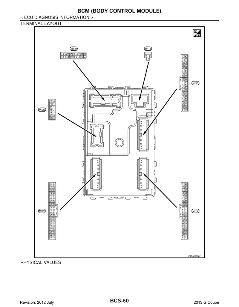
We will be tapping into wires in the following connectors (marked with a number in a circle): M118, M122 and M123.
KP Module Yellow to M118, Pin #3, Brown
KP Module Green to M122, Pin #87, Yellow
KP Module Blue to M123, Pin #146, Sky Blue
KP Module Black to Chassis Ground.
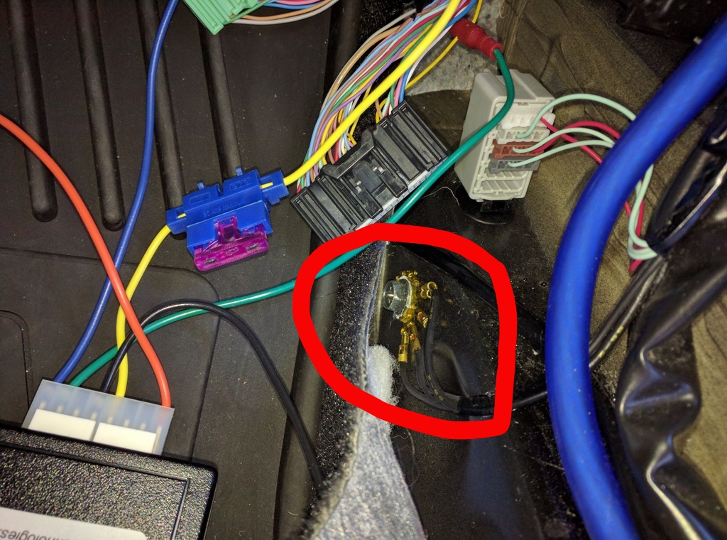
I found an OEM Grounding point below the carpet near the BCM:
Pay particular attention to the KP Green to Pin #87 Yellow connection. There are more than one yellow wires in that harness. Make sure you have the correct one.
Here is a shot of my BCM connections:
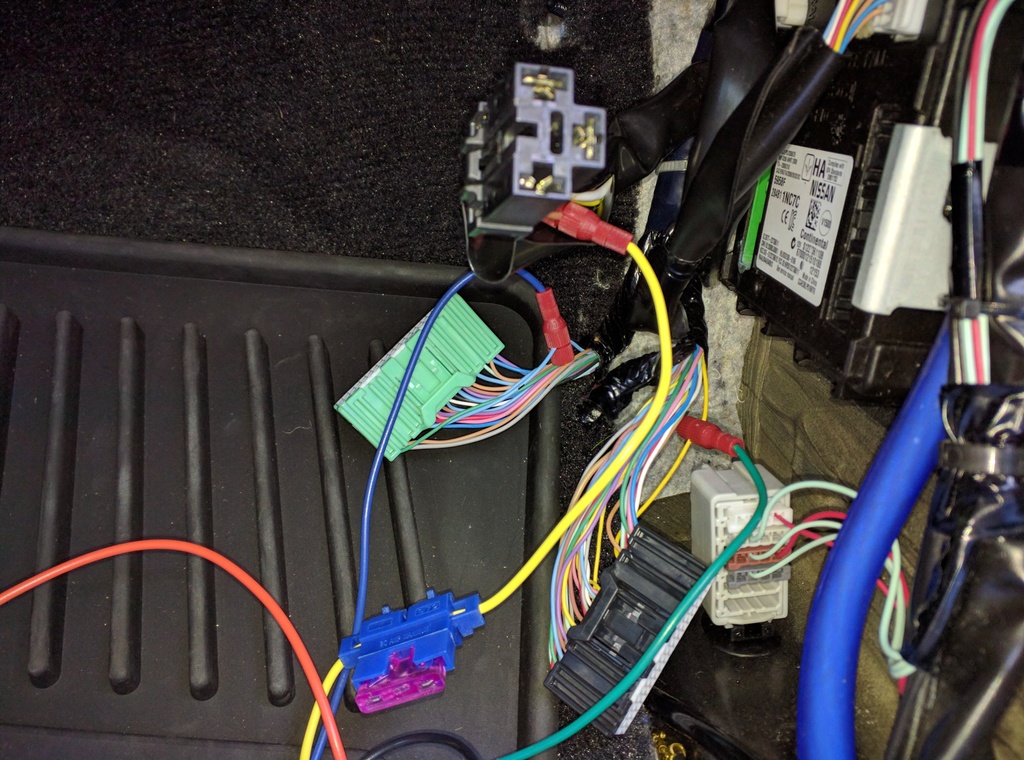
There is a long Orange wire from the KP Module. In addition, there is a length of wire included with the kit (my wire was blue). Both of these need to be passed through the firewall. I chose to use the rubber grommet behind the battery (the same location I used for my amp power wire). Pass both wires through and seal the grommet with silicone when you have everything working.
Now we can look at the IPDM connections:
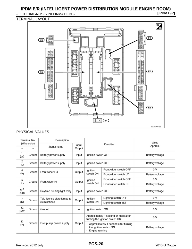
Here we will only be concerned with connector E8, Pins #86 (White) and #87 (Blue). These 2 wires receive the signal from the BCM (through the IPDM) and send it out to the foglights. The KP relay unit is what we will be connecting in the engine bay. Here is a shot of the whole relay unit and IPDM:
This was the most tricky part of the installation, as none of the wire colors matched the printed instructions provided by KP. Relays all do the same thing, they take a signal trigger pulse to activate another circuit. Some are fancier than others and in this case, we are using signal wires to fake out the BCM. Here is my lame diagram of the relay as I received it from KP. Pay more attention to the Pin #s than the wire colors to make sure you get it right.
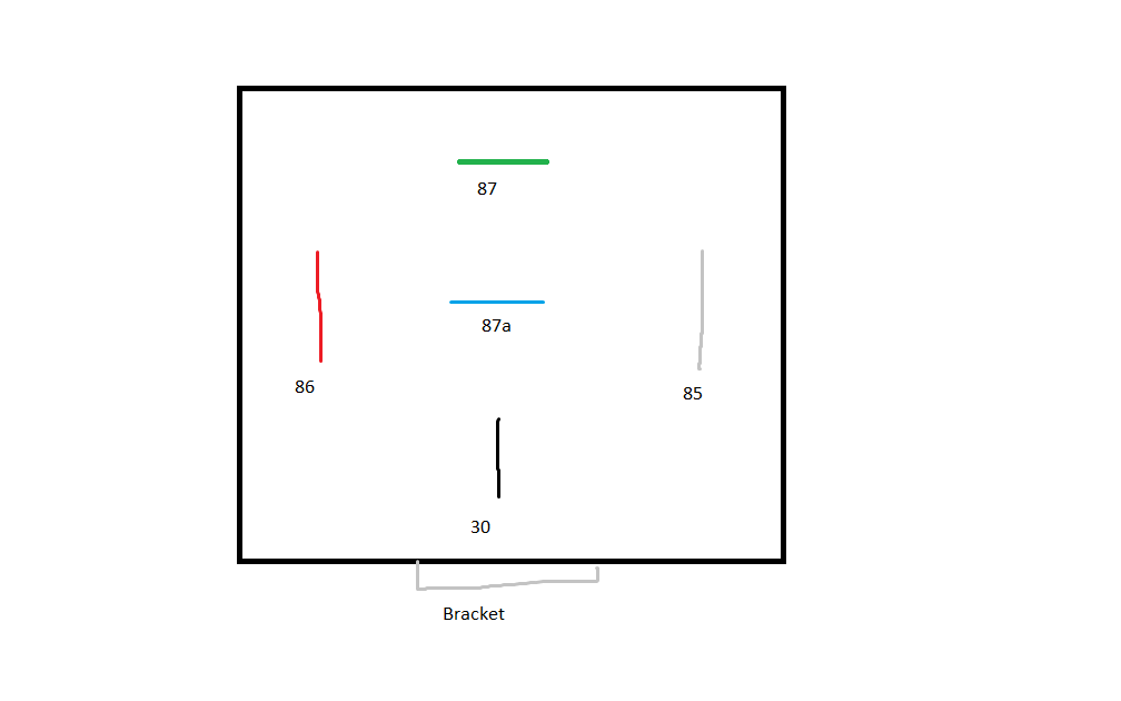
On the IPDM, find the Blue wire at Pin #87. You may want to remove some of the electrical tape bundling the wires so you have enough length to work with. Cut the blue wire and connect the side that goes to the IPDM to the blue wire on the relay that connects to pin 87a. Set the other end aside for a minute. Find the White wire on the IPDM Pin #86 and cut the wire. Tape the end that goes into the IPDM so it is insulated. Take both of the remaining White and Blue wires (the ends that go to the fog lights) and connect them to the Black wire on the relay at Pin #30.
The Orange wire connects to the White wire on the relay at Pin #85.
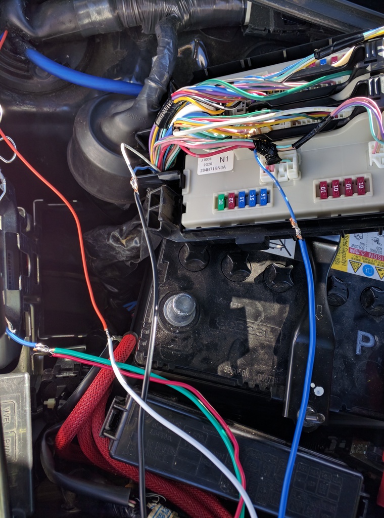
The other wire we ran through the firewall connects to the relay to both the Red and Green wires at Pins #86 and #87 respectively. The final connection for this wire is back near the BCM. Tap this line into the KP Module Yellow wire, between the fuse holder and the module. In the shot of the BCM connections above, you want the portion of the yellow wire going from the fuse holder off the bottom of the picture. Here is a final shot of the underhood connections:
It may sound more intimidating than it actually is, but the end result is foglights that work without the headlights on. Nice!
Installation on my 2013 G37xS Coupe.
This product allows operation of the foglights independent of the headlights. Wiring instructions were quite difficult to figure out, as the KP forums have old posts or links to old/non-existent posts. Thankfully, Kevin from KP has enough info available that I was able to piece instructions together to figure things out along with the FSM diagrams. I can now share this info with you!
The foglights are controlled via the Body Control Module, which on older G's was located under the drivers side kick panel. However, on my 2013 xS coupe, its located on the passenger side kick panel.
The signals go from the BCM to the IPDM (Intelligent Power Distribution Module) in the engine bay, which then sends power to the fogs in the bumper.
The module has 2 parts: The module unit itself (which connects to the BCM) and a relay unit mounted under the hood that gets the signal from the IPDM. It basically intercepts the signal from the turn signal stalk switch to the BCM and feeds the BCM whatever signal it needs to stay happy. Then it sends the signal to the relay which then powers the lights.
For the install, I used Posi-Taps (http://www.ebay.com/itm/221407703981?var=520280288509) for the BCM connections and soldered the relay connections.
Now that we understand how the system works, lets look at some diagrams:
Here is the BCM

We will be tapping into wires in the following connectors (marked with a number in a circle): M118, M122 and M123.
KP Module Yellow to M118, Pin #3, Brown
KP Module Green to M122, Pin #87, Yellow
KP Module Blue to M123, Pin #146, Sky Blue
KP Module Black to Chassis Ground.
I found an OEM Grounding point below the carpet near the BCM:

Pay particular attention to the KP Green to Pin #87 Yellow connection. There are more than one yellow wires in that harness. Make sure you have the correct one.
Here is a shot of my BCM connections:

There is a long Orange wire from the KP Module. In addition, there is a length of wire included with the kit (my wire was blue). Both of these need to be passed through the firewall. I chose to use the rubber grommet behind the battery (the same location I used for my amp power wire). Pass both wires through and seal the grommet with silicone when you have everything working.
Now we can look at the IPDM connections:

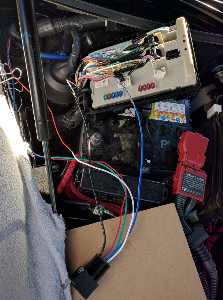
Here we will only be concerned with connector E8, Pins #86 (White) and #87 (Blue). These 2 wires receive the signal from the BCM (through the IPDM) and send it out to the foglights. The KP relay unit is what we will be connecting in the engine bay. Here is a shot of the whole relay unit and IPDM:

This was the most tricky part of the installation, as none of the wire colors matched the printed instructions provided by KP. Relays all do the same thing, they take a signal trigger pulse to activate another circuit. Some are fancier than others and in this case, we are using signal wires to fake out the BCM. Here is my lame diagram of the relay as I received it from KP. Pay more attention to the Pin #s than the wire colors to make sure you get it right.

On the IPDM, find the Blue wire at Pin #87. You may want to remove some of the electrical tape bundling the wires so you have enough length to work with. Cut the blue wire and connect the side that goes to the IPDM to the blue wire on the relay that connects to pin 87a. Set the other end aside for a minute. Find the White wire on the IPDM Pin #86 and cut the wire. Tape the end that goes into the IPDM so it is insulated. Take both of the remaining White and Blue wires (the ends that go to the fog lights) and connect them to the Black wire on the relay at Pin #30.
The Orange wire connects to the White wire on the relay at Pin #85.
The other wire we ran through the firewall connects to the relay to both the Red and Green wires at Pins #86 and #87 respectively. The final connection for this wire is back near the BCM. Tap this line into the KP Module Yellow wire, between the fuse holder and the module. In the shot of the BCM connections above, you want the portion of the yellow wire going from the fuse holder off the bottom of the picture. Here is a final shot of the underhood connections:

It may sound more intimidating than it actually is, but the end result is foglights that work without the headlights on. Nice!


The following users liked this post:
Lego_Maniac (09-07-2016)

 09-09-2016, 10:24 AM
#3
Premier Member
Thread Starter
Kevin from KP has been responsive to my email questions, so these products are still supported. Dust it off, take a look at my write up and see if it helps to figure it out. Everything you need is here. As always, check and double check your wiring. I do not have a multimeter and just used my amazing powers of deduction to get it figured out!
09-23-2016, 01:02 PM
#4

Well Done! I can 100% attest to it being intimidating at first, but once you do your homework and lay everything out it's much easier.
One questions, they function without any issues for you? I installed mine, I believe 2 years ago, and if my fogs are off and I use my left blinker my fogs turn on. To remedy this, I use my fogs as DRLs. I'll have to re-check my wiring, but I'm 95% positive I installed the same way as you did.
One questions, they function without any issues for you? I installed mine, I believe 2 years ago, and if my fogs are off and I use my left blinker my fogs turn on. To remedy this, I use my fogs as DRLs. I'll have to re-check my wiring, but I'm 95% positive I installed the same way as you did.
09-23-2016, 01:36 PM
#5
Premier Member
Thread Starter
The only issue I've had is the dinky 3A fuse blowing. I replaced it with a 5A fuse and it has been fine ever since. KP says I should tap the blue wire running through the firewall to the brown RAP wire directly (fused at 10A), but my foglights are LED and I doubt they draw that much power, even at startup. I will run with the 5A fuses to see if that resolves my issue.
As to your specific question, you need to re-trace your wires. Something is crossed up as your turn signals should not affect your fogs.
As to your specific question, you need to re-trace your wires. Something is crossed up as your turn signals should not affect your fogs.
11-03-2016, 04:07 PM
#6
Registered Member

hey dwb993, thx for the useful write-up...
got a quick question to ask, with the fog lights off, when u switch on left signal, does the fog lights turn on with the signal?
because mine does and also a few other sedan owners, was wondering if it does the same on coupes? thanks.
got a quick question to ask, with the fog lights off, when u switch on left signal, does the fog lights turn on with the signal?
because mine does and also a few other sedan owners, was wondering if it does the same on coupes? thanks.
11-04-2016, 11:58 AM
#7
Premier Member
Thread Starter
Sounds like the same issue Dang reported. I have not seen similar behavior on my setup.
Trending Topics
11-14-2016, 10:02 AM
#8
Premier Member
Thread Starter
So, one of my foglights is malfunctioning. I have new units on the way.
I did want to mention that I am seeing the symptoms reported earlier (foglight activates with turn signal), but I need to determine the cause. I will look at it in detail when I receive the replacement units.
I did want to mention that I am seeing the symptoms reported earlier (foglight activates with turn signal), but I need to determine the cause. I will look at it in detail when I receive the replacement units.
 01-26-2017, 03:33 PM
#10
Premier Member
Thread Starter
No, not yet. But to be honest, since it turned cold I really have not spent any time looking into it. I will post an update once I do.
 06-09-2019, 08:05 PM
#12
Premier Member
Thread Starter
I get this behavior on my coupe, as well. My solution is to run my parking lights with the fogs, but I know that is not the correct solution. I have not had a chance to report the behavior to Kevin. I'll shoot him an email and see if he replies.
06-11-2019, 03:56 PM
#13
Premier Member
Thread Starter
Here is the response from Kevin. I plan to try his suggestion re: the green wire this weekend and will report back.
David,
Does it do it all the time or just occasionally? From memory the left turn signal shares either the input or output on the BCM (so there is a connection between the left turn signal and fog light switch that wouldn't make this totally random).
If it does it all the time I would suggest swapping the blue and green wire on the module and see if that changes anything. One other thing I would do, if it happens every time, is verify that you have in fact connected to the two correct wires in the BCM harness.
The module works by looking for a voltage signal on the "output" wire. If the signal is present it looks for the same voltage in the input wire (to verify the switch is closed). If you connect one wire, or the other, to constant power (or a signal that has constant power out of sync with the switching matrix) it can make the module switch the output on with other devices on the same channel of the matrix are activated.
If it only sporadically acts up I would check to make sure all your connections are soldered cleanly and you have a good ground. It could be possible that the turn signal switching is causing some noise that is interfering with the module. Depending on when you bought the module there should be a diagnostic LED on the circuit board that is visible through the opening that the wire harness plugs in to that comes on whenever there is a valid signal on the wires. It may be easier to troubleshoot the module using that LED as opposed to using the actual fog lights. It may also be possible to remove the LED from the circuit board and remotely mount it for easier viewing to see if you can establish a pattern.
Thank you,
Kevin Pierson