DIY: Rear Sport brake rotors and pads
 01-08-2017, 11:34 PM
#1

Rear Sport brake rotors and pads
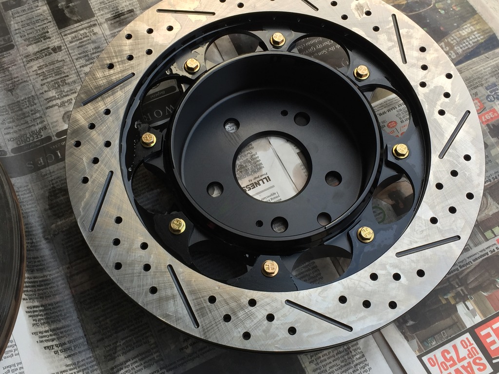
***NOTE, in the photos of the Z1 rotors installed, the leading edge of the slots, the part that'll come into contact with the pads first, is on the bottom. That's wrong, should be the top of the slot. This actually has to do with the curved vanes internally and not the slots themselves. It's simply a visual cue as to which way to install the rotors. The curved vane direction is more important.****
Since there isn't a DIY on changing out the rear rotors and pads for the Akebono brakes (Sport, IPL), I thought I'd go ahead and snap photos as I went through the installation today and post up a how to.
This is how I did things and it's only a guide. I suggest some experience is necessary along with a shop manual, the appropriate mechanical skills, etc...you do this at your own peril and I assume no responsibility nor intend for this to be an 100% correct guide. So do your homework.
First, it's not much more difficult than installing the front rotors and pads. There's one extra step and that's adjusting the parking brake. It's easy and I'l get to that shortly.
Time wise, it took me about two hours including cleanup and cleaning of the stock brake hardware parts. If you have new pins, springs and clips, it'll save you about 20 minutes.
I'm installing Z1 two-piece rear rotors but it's the same for any rotor make that bolts on like OEM.
Some of these steps are particular to those with an automatic G37.
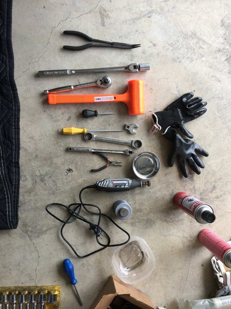
Tools and supplies needed:
-3/8" or 1/2" torque wrench. You'll need two readings, 60ft. lbs. and 80ft. lbs so make sure your wrench can cover both.
-1/2" breaker bar
-19mm socket, short
-Three inch, 1/2" extension
-19mm crow's foot (optional)
-Short phillips head screwdriver
-1/2" ratcheting wrench
-19mm closed wrench (ratcheting or otherwise)
-small punch or thin screwdriver to push the caliper pins out
-dremel with a small bristle head for cleaning off rust
-dead blow hammer
-small pliers
-angle pliers (optional)
-Flat head screwdriver
-magnetic pan to hold small parts
-brake cleaner
-high temp grease
-anti-sieze
-small plastic container to soak brake hardware in cleaner
-lots of paper towels
-small flashlight
-crowbar (optional)
-piston spreader (optional)
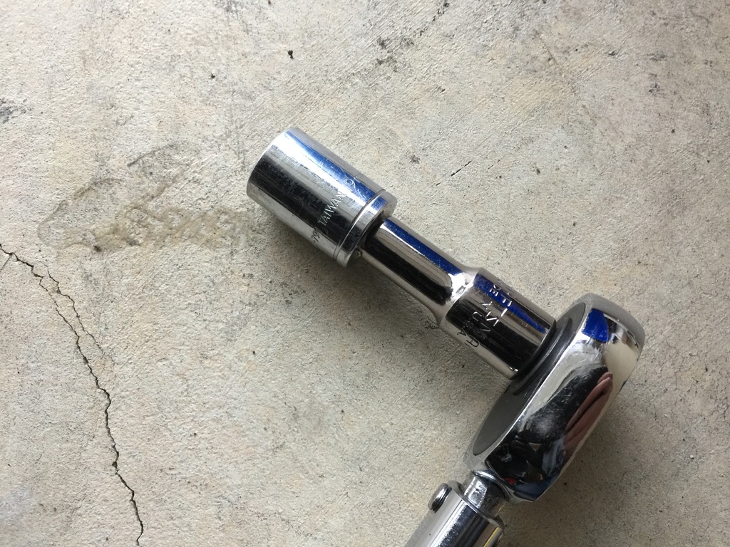
A note on the 19mm crow's foot. Because of the traction link, the lower caliper to upright bolt is tough to get to. I saw an installation where he used a crow's foot to torque to spec. I found I didn't need it. First, my 3/8" torque wrench didn't go up to 60ft.lbs. and I couldn't use the crow's foot wrench. I ended up putting on a 3" extension in between the 19mm socket and my 1/2" torque wrench and that worked just fine. So if you have a short extension, you should be ok without the crow's foot.
Here's a pic of what worked for me:
First, put wheel chocks under the front wheels. Loosen the rear lug nuts before jacking up the car. Jack up the rear (I slide my jack under the differential pumpkin) and put stands on either side of the car securely.
Remove the lugs, then the wheels. I have spacers on the rear so I needed to remove those too.
With my spacers off I could see this little job. It's a rubber grommet that seals the rear parking brake adjustment port. You can just use a flat head screwdriver to pop it out. Don't loose it and don't forget to re-install it!
The next step is to remove the stock brake pad hardware and brake pads.
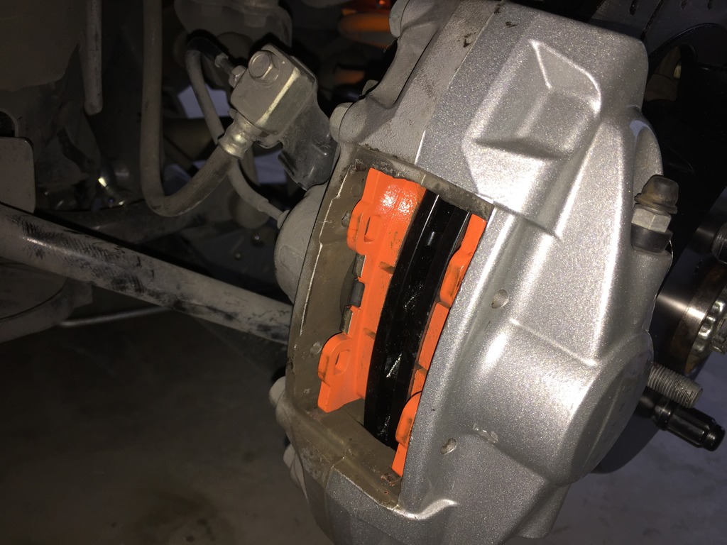
In the photo below, you can see the top of two small cotter clips (red arrows). Use a flashlight as it helps to see them. They're quite small. If you cannot see them, the third red arrow is one of two pins that keep the pads in the caliper. They rotate easily with a phillips head screwdriver. The head is on the inboard side so you'll need to use a short phillips head to rotate the pins until the cotter pins are visible. Pull them straight out. They come out easily so don't use a ton of force and send them flying. They'll be hard to find.
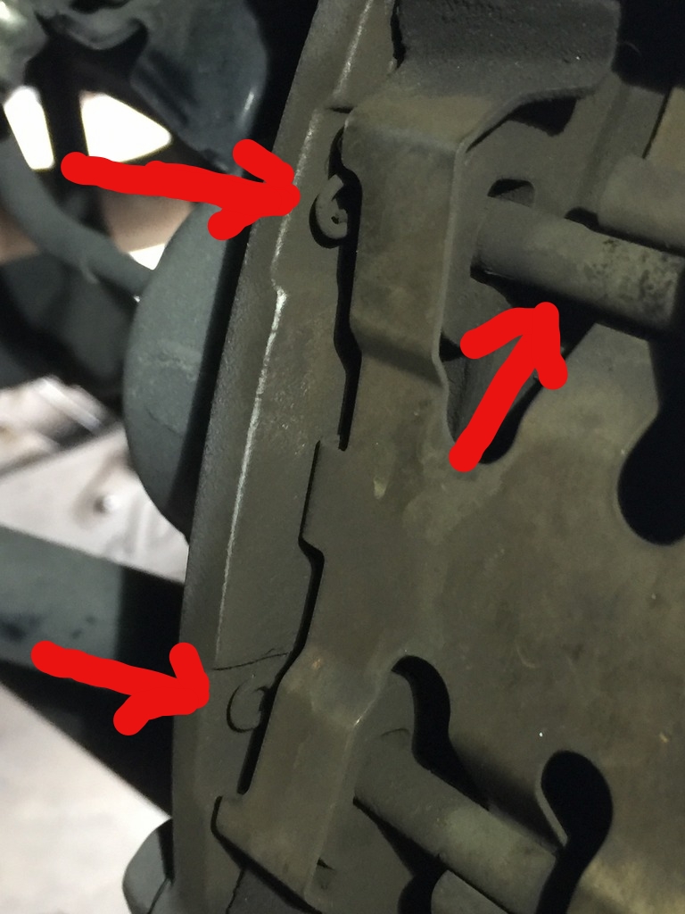
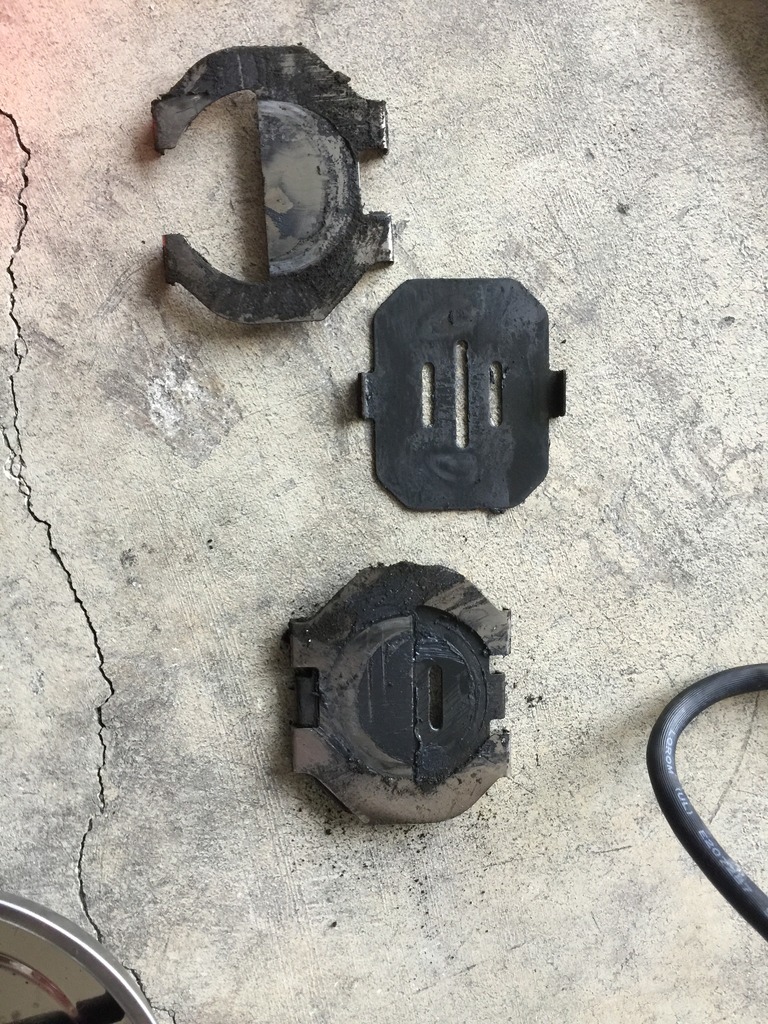
Here are the pins removed and secure in a magnetized dish so they can't get lost.
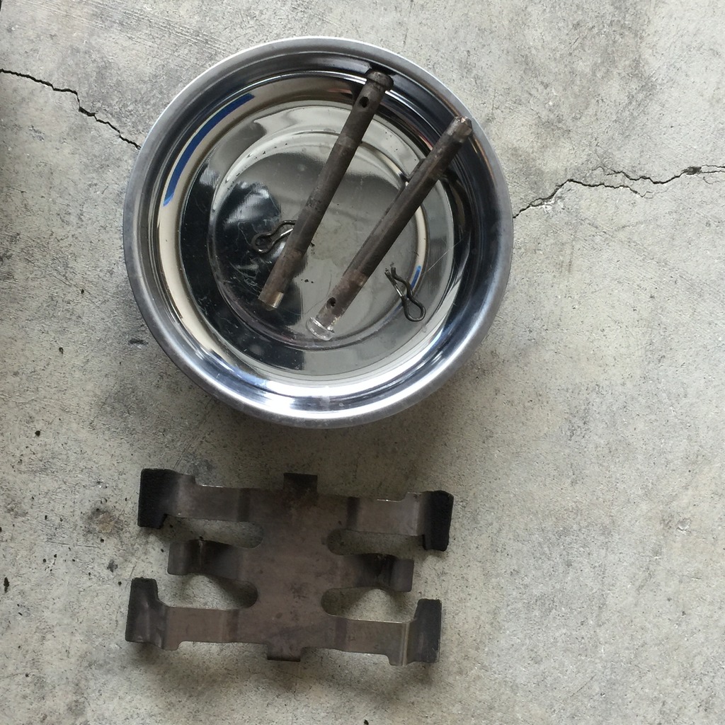
Once the clips are removed, you can then push the two caliper pins out. They push inwards. So you'll need to take your punch or screwdriver and push from the outside to the inboard side. They come out fairly easily.
Once those are removed, the brake pad spring will likely pop out. If not just lift it out with your fingers as there's nothing holding it in at this point.
You should have two clips, two pins and one spring per side.
With the caliper hardware removed, it's time to remove the brake pads. They can be a bit fussy and you may need to use a combination of a flat head screwdriver or various pliers inserted into the top and bottom brake pad holes on the pads themselves. Alternate between the two and wiggle them a bit and pry a bit if need be. They can get hung up on a rotor lip or on the shims but they will come out.
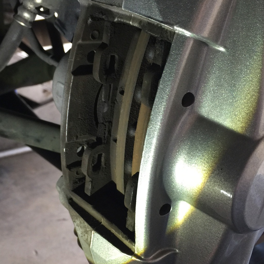
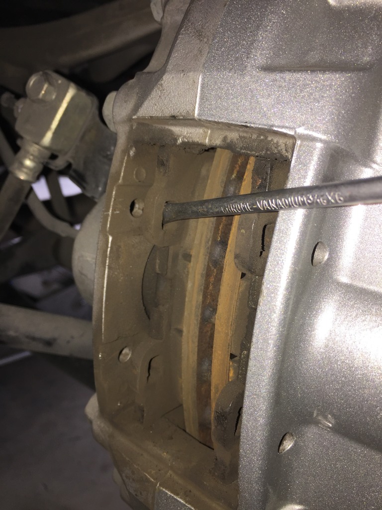
Pads are out! These are the stock Sport Akebono pads. They had plenty of life left at 30,000 miles. I put each pad in a separate bag and labeled them inboard and outboard. Note, the inboard pad will have the wear indicator clip, the outboard does not.
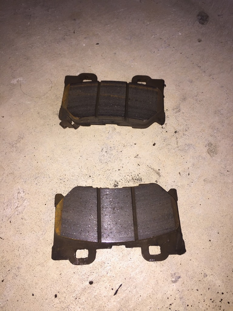
Take the backing plates or shims off the back of the stock pads. They only go on one way and take note of the marks made by the piston calipers. That'll help you determine what goes where when it's time to assemble. But they basically can only go on one way. At this point, I dumped all the hardware into a vat of brake cleaner to soak.
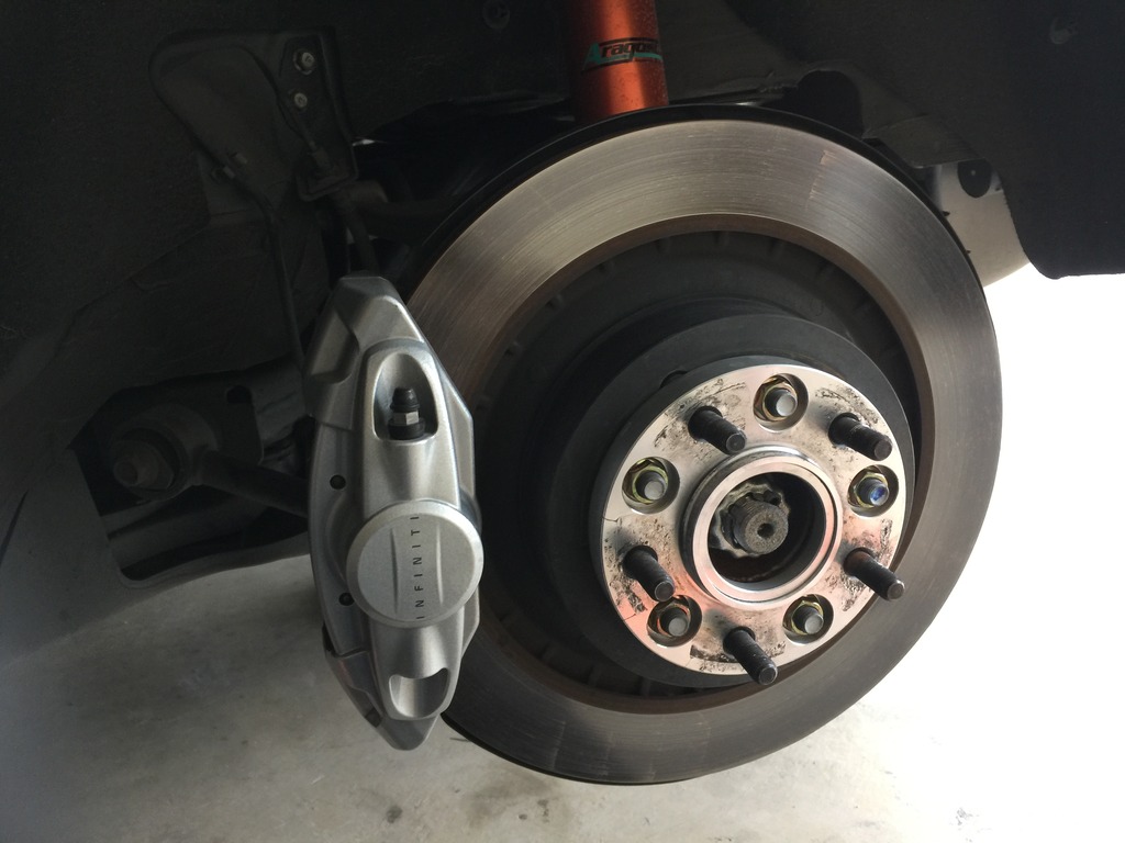
The next step is to remove the rear caliper. It's held on by TWO 19mm bolts that are torqued to 60ft lbs. I found it easiest to use a 19mm ratcheting wrench and hit it with a rubber mallet. Not too hard to get them off. In the photo, the camera is pointed from the inside to the outside so you're actually looking at the back (inboard side of the caliper).
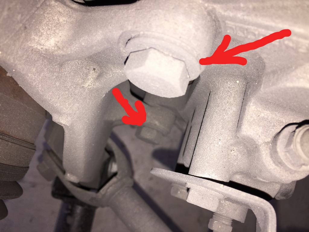
You can see the traction arm at the bottom of the photo next to the bottom caliper bolt. This is what causes you to either use a crow's foot or an extension.
Since there isn't a DIY on changing out the rear rotors and pads for the Akebono brakes (Sport, IPL), I thought I'd go ahead and snap photos as I went through the installation today and post up a how to.
This is how I did things and it's only a guide. I suggest some experience is necessary along with a shop manual, the appropriate mechanical skills, etc...you do this at your own peril and I assume no responsibility nor intend for this to be an 100% correct guide. So do your homework.
First, it's not much more difficult than installing the front rotors and pads. There's one extra step and that's adjusting the parking brake. It's easy and I'l get to that shortly.
Time wise, it took me about two hours including cleanup and cleaning of the stock brake hardware parts. If you have new pins, springs and clips, it'll save you about 20 minutes.
I'm installing Z1 two-piece rear rotors but it's the same for any rotor make that bolts on like OEM.
Some of these steps are particular to those with an automatic G37.
Tools and supplies needed:
-3/8" or 1/2" torque wrench. You'll need two readings, 60ft. lbs. and 80ft. lbs so make sure your wrench can cover both.
-1/2" breaker bar
-19mm socket, short
-Three inch, 1/2" extension
-19mm crow's foot (optional)
-Short phillips head screwdriver
-1/2" ratcheting wrench
-19mm closed wrench (ratcheting or otherwise)
-small punch or thin screwdriver to push the caliper pins out
-dremel with a small bristle head for cleaning off rust
-dead blow hammer
-small pliers
-angle pliers (optional)
-Flat head screwdriver
-magnetic pan to hold small parts
-brake cleaner
-high temp grease
-anti-sieze
-small plastic container to soak brake hardware in cleaner
-lots of paper towels
-small flashlight
-crowbar (optional)
-piston spreader (optional)
A note on the 19mm crow's foot. Because of the traction link, the lower caliper to upright bolt is tough to get to. I saw an installation where he used a crow's foot to torque to spec. I found I didn't need it. First, my 3/8" torque wrench didn't go up to 60ft.lbs. and I couldn't use the crow's foot wrench. I ended up putting on a 3" extension in between the 19mm socket and my 1/2" torque wrench and that worked just fine. So if you have a short extension, you should be ok without the crow's foot.
Here's a pic of what worked for me:
First, put wheel chocks under the front wheels. Loosen the rear lug nuts before jacking up the car. Jack up the rear (I slide my jack under the differential pumpkin) and put stands on either side of the car securely.
Remove the lugs, then the wheels. I have spacers on the rear so I needed to remove those too.
With my spacers off I could see this little job. It's a rubber grommet that seals the rear parking brake adjustment port. You can just use a flat head screwdriver to pop it out. Don't loose it and don't forget to re-install it!
The next step is to remove the stock brake pad hardware and brake pads.
In the photo below, you can see the top of two small cotter clips (red arrows). Use a flashlight as it helps to see them. They're quite small. If you cannot see them, the third red arrow is one of two pins that keep the pads in the caliper. They rotate easily with a phillips head screwdriver. The head is on the inboard side so you'll need to use a short phillips head to rotate the pins until the cotter pins are visible. Pull them straight out. They come out easily so don't use a ton of force and send them flying. They'll be hard to find.
Here are the pins removed and secure in a magnetized dish so they can't get lost.
Once the clips are removed, you can then push the two caliper pins out. They push inwards. So you'll need to take your punch or screwdriver and push from the outside to the inboard side. They come out fairly easily.
Once those are removed, the brake pad spring will likely pop out. If not just lift it out with your fingers as there's nothing holding it in at this point.
You should have two clips, two pins and one spring per side.
With the caliper hardware removed, it's time to remove the brake pads. They can be a bit fussy and you may need to use a combination of a flat head screwdriver or various pliers inserted into the top and bottom brake pad holes on the pads themselves. Alternate between the two and wiggle them a bit and pry a bit if need be. They can get hung up on a rotor lip or on the shims but they will come out.
Pads are out! These are the stock Sport Akebono pads. They had plenty of life left at 30,000 miles. I put each pad in a separate bag and labeled them inboard and outboard. Note, the inboard pad will have the wear indicator clip, the outboard does not.
Take the backing plates or shims off the back of the stock pads. They only go on one way and take note of the marks made by the piston calipers. That'll help you determine what goes where when it's time to assemble. But they basically can only go on one way. At this point, I dumped all the hardware into a vat of brake cleaner to soak.
The next step is to remove the rear caliper. It's held on by TWO 19mm bolts that are torqued to 60ft lbs. I found it easiest to use a 19mm ratcheting wrench and hit it with a rubber mallet. Not too hard to get them off. In the photo, the camera is pointed from the inside to the outside so you're actually looking at the back (inboard side of the caliper).
You can see the traction arm at the bottom of the photo next to the bottom caliper bolt. This is what causes you to either use a crow's foot or an extension.
Last edited by Ape Factory; 01-10-2017 at 10:58 AM.

The following users liked this post:
MStrike (11-04-2021)
01-09-2017, 12:10 AM
#2
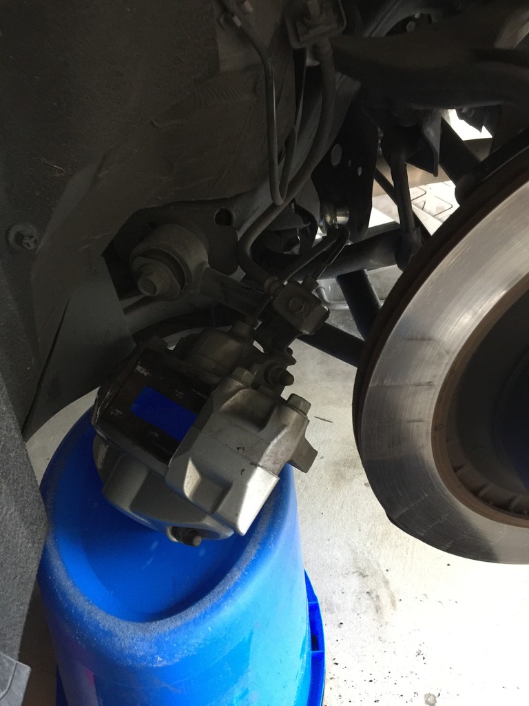
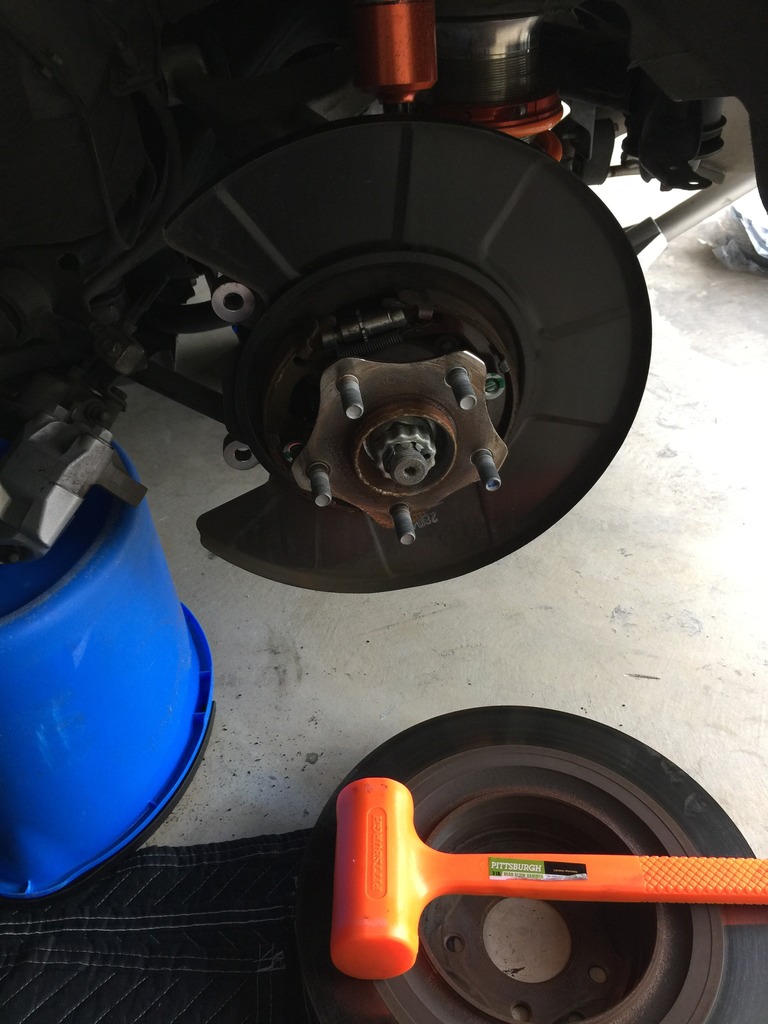
Once the two 19mm bolts are removed, the caliper will fall right off so be sure to support it.
You'll need a blue bucket a bit over a foot tall, turned upside down, to support the caliper and not put stress on the brake lines.
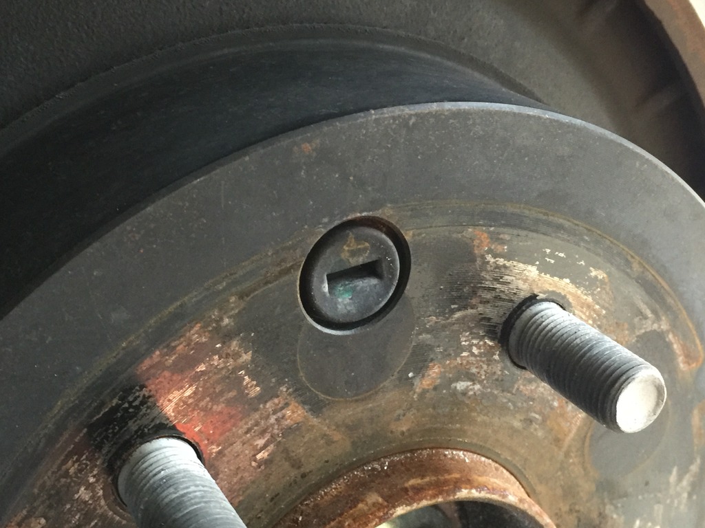
I'm going to cheat a bit here (we haven't gotten to this point) but it's helpful to see what the parking brake adjustment mechanism looks like.
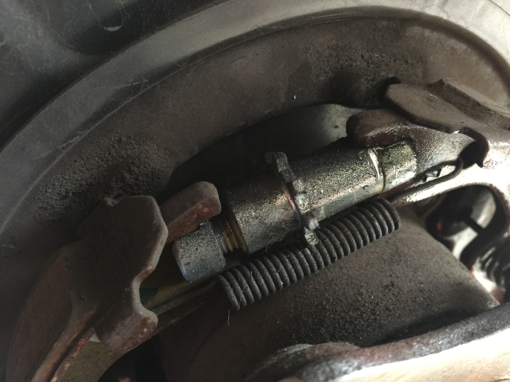
If your car has fairly low miles and isn't from the rust belt, the rotors may come off with a few hits of a dead blow hammer. Mine did and it was quite easy. I did not have to adjust the parking brake mechanism to full loose in order to take them off.
If you find the parking brake needs to be loosened, you'll need to do this now with a flat head screwdriver.
If you have a manual-equipped G, take it out of gear and make sure the parking brake is disengaged. Rotate the brake disk until the parking brake adjustment port (hole) allows you to see the adjuster with a flashlight.
If you have an auto-equipped car, you'll need to have your keys. Get in the driver's seat and DO NOT put your foot on the brake. Hit the start button twice until the accessories are all on but the engine is NOT on. THEN put your foot on the brake and shift the car into neutral. Make sure your lights are off Go back to the rear wheel and rotate the disk until you can see the brake adjuster through the access port. Go back and turn car off.
Let's look at that photo one more time. The adjuster is the thing in the middle with the teeth sticking out. It's basically a turnbuckle and you adjust it through the port with the flat head screwdriver by rotating it via the teeth. The spring below keeps it from rotating on its own so you need to get the screwdriver head in between the teeth and the spring. If I remember correctly, rotate it down to loosen the brake, up to tighten it. It may be the reverse. The gap visible on the left side will grow or shrink and you can see it through the port to figure out which way you need to turn it.
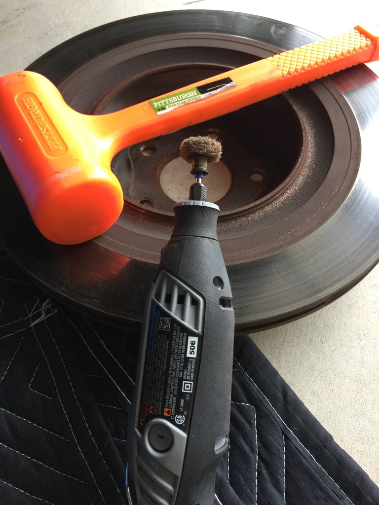
Here's the rear hub after taking off the rear brake disk. You'll want to clean it and remove the rust.
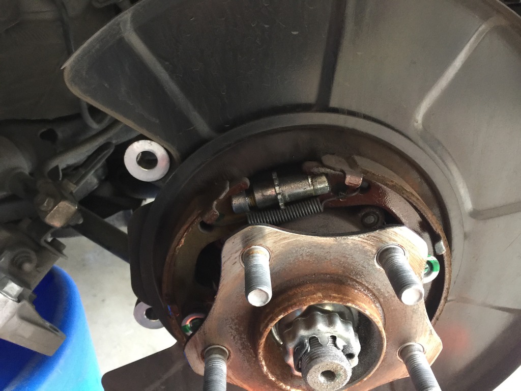
I used a dremel. There's something called a hub cleaning tool but they're expensive, like $40 and you'll use it maybe once in your lifetime. It's a cylinder, hollow in the middle, and attaches to your cordless drill. Has an abrasive disk on the end and you can slide it over the top of the wheel stud and clean the hub surface. The dremel, with the little abrasive disk on the end, worked just as well.
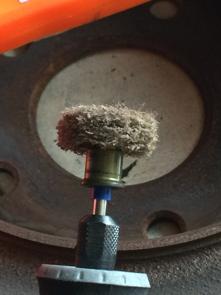
After scrubbing the face with the dremel, I spray it down with brake fluid and wipe everything off.
The next step is your first use of high temp grease. I wipe on a light coat with a clean finger and then wipe it off with a paper towel. It'll leave a very thin layer behind and it should help keep rust at bay. I have anodized aluminum hats so they won't bond to the steel hubs.
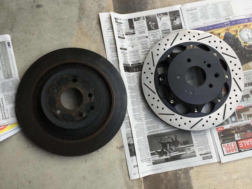
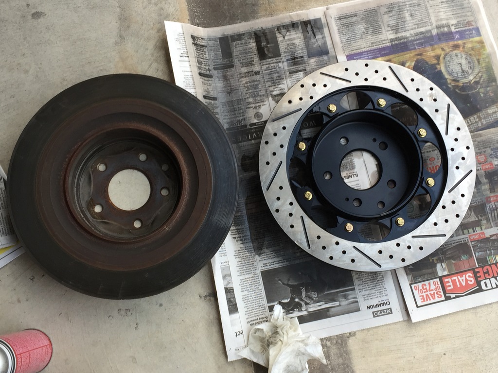
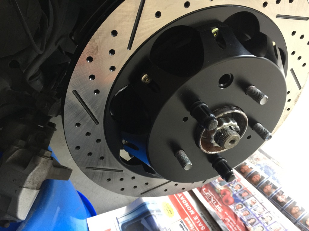
It's sexy time! Stock (duh) on the left, Z1 two-piece on the right. I think they're about five pounds lighter than the stock disks. The front Z1 disks are 10 pounds lighter.
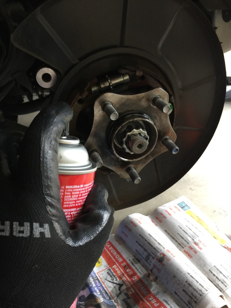
I put the new rotor on some newspaper and spray it down thoroughly, both sides, to remove any machining oil or other contaminants. I then wipe the disk faces off with clean paper towels.
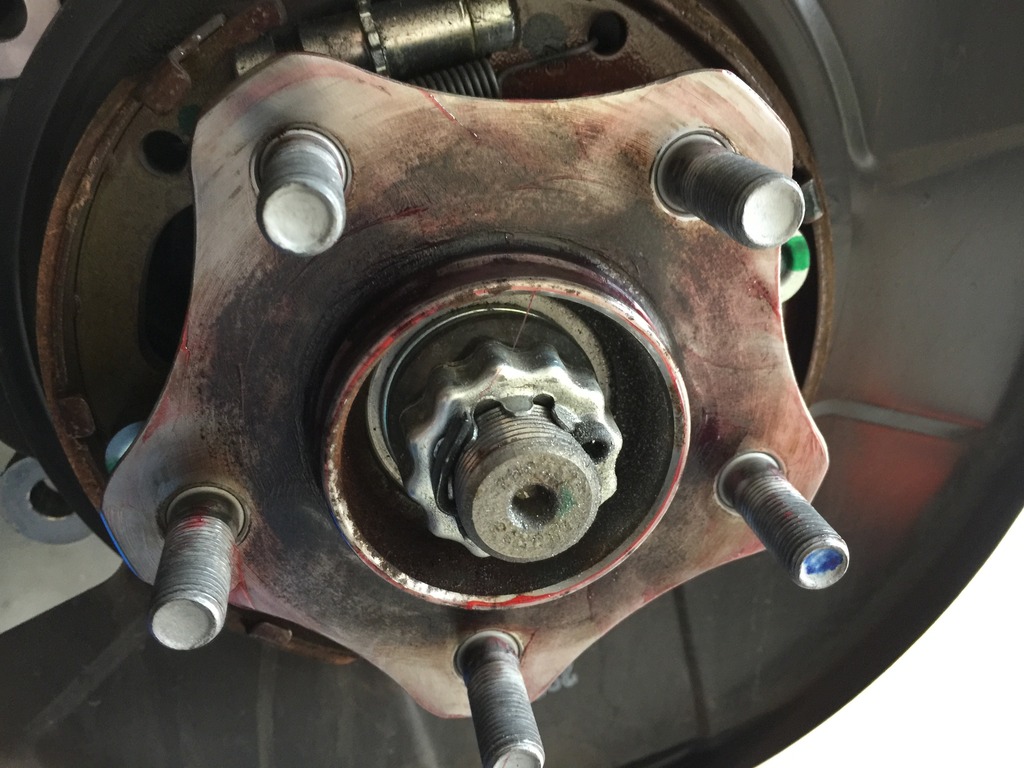
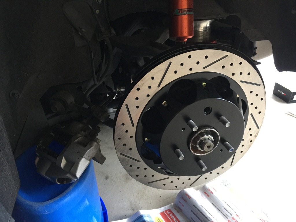
Now that it's clean, install the disk on the hub/wheel studs and make sure the parking brake adjustment port is lined up with the adjuster.
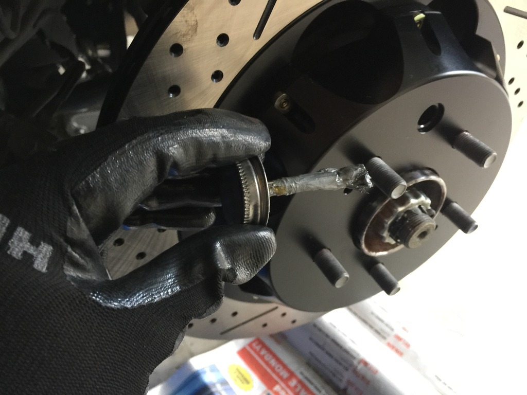
I use anti-seize on the studs.
I then screw on two of the wheel nuts to make sure the brake disk is sitting squarely and firmly against the hub.
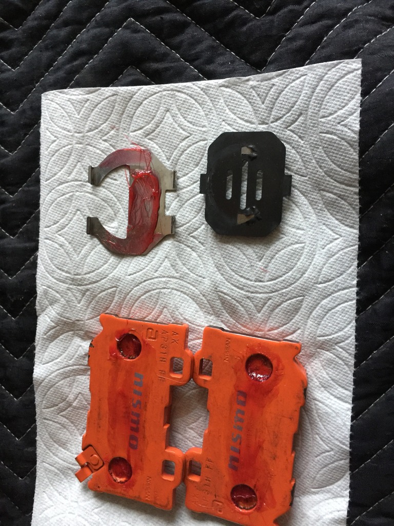
You're now ready to install your new (or used) pads and brake caliper hardware. I've had the hardware soaking so I remove all of it and wipe it down til it looks fairly clean. It's probably best just to purchase new hardware but no one had it in stock and I thought, just maybe, the Nismo pads would come with new hardware. They don't. My hardware was in good shape so I reused it.
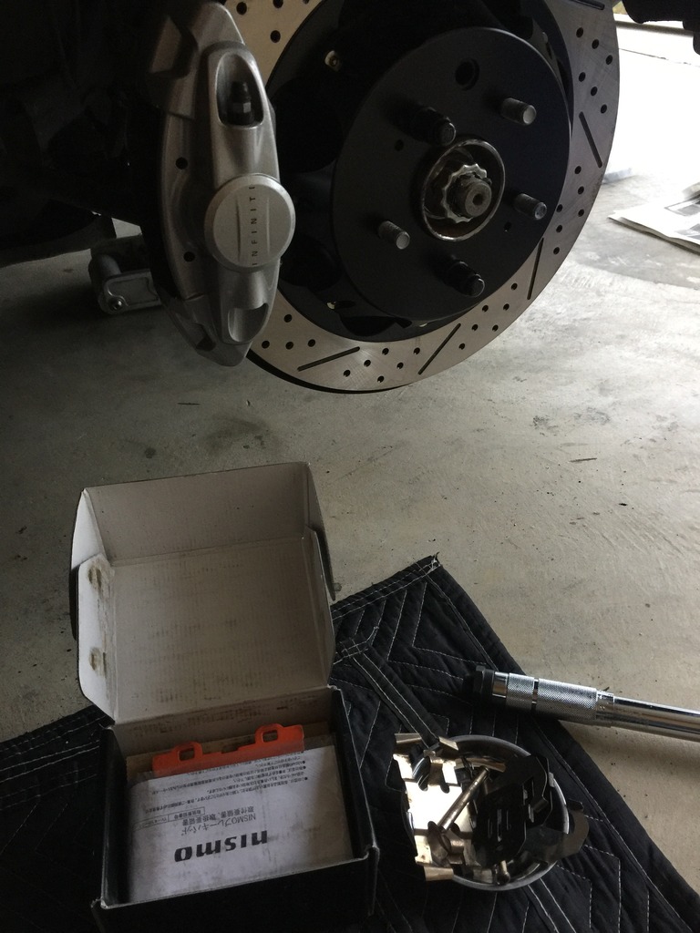
Business side of the Nismo rear pads.
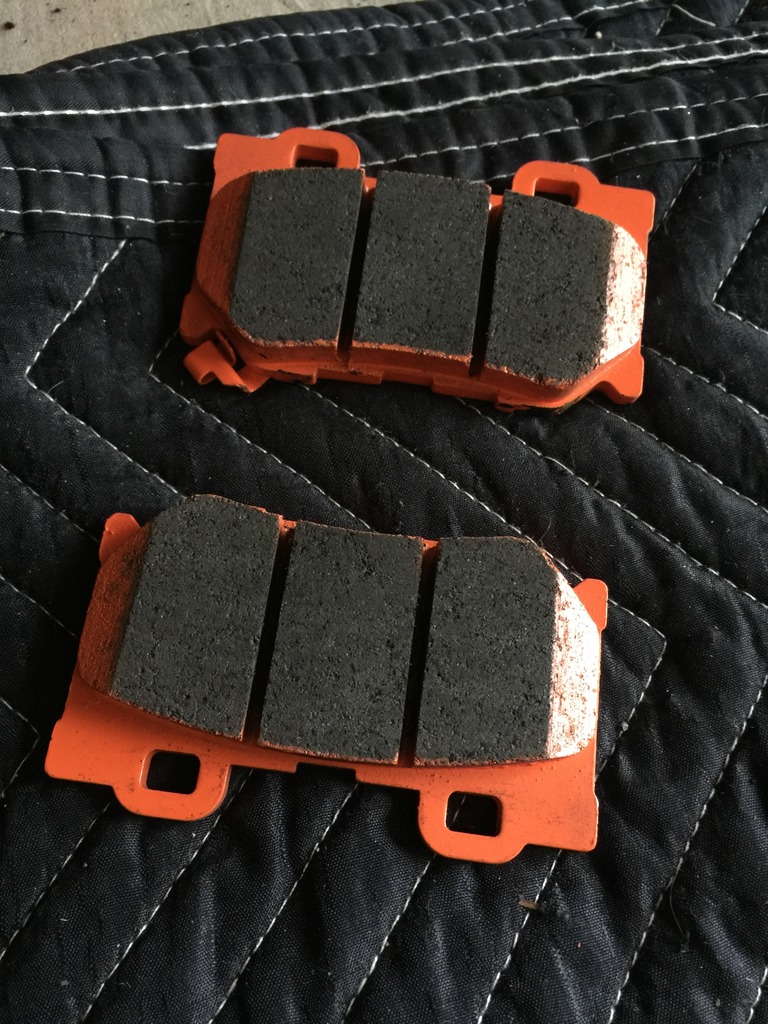
Nismo pads with the shims ready for installation.
I used high temp grease between the pads and the shims. The shims are two-piece and there's grease between them as well. I also put a very small amount on all four corners of the pad backing plate where the spring will touch it.
I didn't take any photos of the next step as it's too difficult to do both at the same time. The next step is to push the caliper pistons back into the caliper.
FIRST, pop your hood and open the brake master cylinder access door on the driver's side. Open your brake fluid reservoir.
Pushing the pistons back in will facilitate sliding the pads back in. If you're using new pads, they'll be thicker than the ones you took out and they won't just slide back in without pushing the pistons in first. I don't use a piston spreader, I just gingerly push them back in with the tools at hand. Mine were in good shape and slid in fairly easily.
Once that's done and you've reinstalled the shims onto your new pad, you can slide them back in. It'll take a bit of wiggling top to bottom and a gentle tap from a rubber mallet sometimes helps.
Success, pads in!
Once the pads are in, it's time to install the hardware in reverse order. Place the spring over the caliper opening and pads. Slide the pins in from the inboard to the outboard side. You'll go underneath the outer tabs and over the middle tab so you'll need to push that down as you slide the pin in. Again, it'll take a bit of wiggling to get it through both holes. Once the pins are all the way in, use the phillips head screwdriver to rotate them so the pin holes are accessible and you can slide the cotter pins back in. Do not forget to put them back in otherwise you could have catastrophic brake failure.
You're done! Re-install the wheel and torque the lugs to 80ft. lbs. Follow the bed-in procedure recommended by the manufacturer if there is one.
You'll need a blue bucket a bit over a foot tall, turned upside down, to support the caliper and not put stress on the brake lines.
I'm going to cheat a bit here (we haven't gotten to this point) but it's helpful to see what the parking brake adjustment mechanism looks like.
If your car has fairly low miles and isn't from the rust belt, the rotors may come off with a few hits of a dead blow hammer. Mine did and it was quite easy. I did not have to adjust the parking brake mechanism to full loose in order to take them off.
If you find the parking brake needs to be loosened, you'll need to do this now with a flat head screwdriver.
If you have a manual-equipped G, take it out of gear and make sure the parking brake is disengaged. Rotate the brake disk until the parking brake adjustment port (hole) allows you to see the adjuster with a flashlight.
If you have an auto-equipped car, you'll need to have your keys. Get in the driver's seat and DO NOT put your foot on the brake. Hit the start button twice until the accessories are all on but the engine is NOT on. THEN put your foot on the brake and shift the car into neutral. Make sure your lights are off
Go back to the rear wheel and rotate the disk until you can see the brake adjuster through the access port. Go back and turn car off.Let's look at that photo one more time. The adjuster is the thing in the middle with the teeth sticking out. It's basically a turnbuckle and you adjust it through the port with the flat head screwdriver by rotating it via the teeth. The spring below keeps it from rotating on its own so you need to get the screwdriver head in between the teeth and the spring. If I remember correctly, rotate it down to loosen the brake, up to tighten it. It may be the reverse. The gap visible on the left side will grow or shrink and you can see it through the port to figure out which way you need to turn it.
Here's the rear hub after taking off the rear brake disk. You'll want to clean it and remove the rust.
I used a dremel. There's something called a hub cleaning tool but they're expensive, like $40 and you'll use it maybe once in your lifetime. It's a cylinder, hollow in the middle, and attaches to your cordless drill. Has an abrasive disk on the end and you can slide it over the top of the wheel stud and clean the hub surface. The dremel, with the little abrasive disk on the end, worked just as well.
After scrubbing the face with the dremel, I spray it down with brake fluid and wipe everything off.
The next step is your first use of high temp grease. I wipe on a light coat with a clean finger and then wipe it off with a paper towel. It'll leave a very thin layer behind and it should help keep rust at bay. I have anodized aluminum hats so they won't bond to the steel hubs.
It's sexy time! Stock (duh) on the left, Z1 two-piece on the right. I think they're about five pounds lighter than the stock disks. The front Z1 disks are 10 pounds lighter.
I put the new rotor on some newspaper and spray it down thoroughly, both sides, to remove any machining oil or other contaminants. I then wipe the disk faces off with clean paper towels.
Now that it's clean, install the disk on the hub/wheel studs and make sure the parking brake adjustment port is lined up with the adjuster.
I use anti-seize on the studs.
I then screw on two of the wheel nuts to make sure the brake disk is sitting squarely and firmly against the hub.
You're now ready to install your new (or used) pads and brake caliper hardware. I've had the hardware soaking so I remove all of it and wipe it down til it looks fairly clean. It's probably best just to purchase new hardware but no one had it in stock and I thought, just maybe, the Nismo pads would come with new hardware. They don't. My hardware was in good shape so I reused it.
Business side of the Nismo rear pads.
Nismo pads with the shims ready for installation.
I used high temp grease between the pads and the shims. The shims are two-piece and there's grease between them as well. I also put a very small amount on all four corners of the pad backing plate where the spring will touch it.
I didn't take any photos of the next step as it's too difficult to do both at the same time. The next step is to push the caliper pistons back into the caliper.
FIRST, pop your hood and open the brake master cylinder access door on the driver's side. Open your brake fluid reservoir.
Pushing the pistons back in will facilitate sliding the pads back in. If you're using new pads, they'll be thicker than the ones you took out and they won't just slide back in without pushing the pistons in first. I don't use a piston spreader, I just gingerly push them back in with the tools at hand. Mine were in good shape and slid in fairly easily.
Once that's done and you've reinstalled the shims onto your new pad, you can slide them back in. It'll take a bit of wiggling top to bottom and a gentle tap from a rubber mallet sometimes helps.
Success, pads in!
Once the pads are in, it's time to install the hardware in reverse order. Place the spring over the caliper opening and pads. Slide the pins in from the inboard to the outboard side. You'll go underneath the outer tabs and over the middle tab so you'll need to push that down as you slide the pin in. Again, it'll take a bit of wiggling to get it through both holes. Once the pins are all the way in, use the phillips head screwdriver to rotate them so the pin holes are accessible and you can slide the cotter pins back in. Do not forget to put them back in otherwise you could have catastrophic brake failure.
You're done! Re-install the wheel and torque the lugs to 80ft. lbs. Follow the bed-in procedure recommended by the manufacturer if there is one.
Last edited by Ape Factory; 01-09-2017 at 12:39 PM.
 01-09-2017, 12:37 PM
#4
I think there are a few front sport brake swaps here and on the370z forum as well so I didn't bother to take a whole lot of photos. It's basically the same except there's no parking brake (duh) and the two bolts that hold the caliper to the suspension upright are 21mm and at 90ft. lbs. There are also three 12mm bolts which hold the metal brake line in place which must be removed to free up wiggle room to position the caliper to the side. I believe the torque specs on those are about 10ft. lbs so not tight at all. Other than that, same thing with the pins, clips, etc...
The following users liked this post:
MStrike (11-04-2021)
 . Good news is I am replacing one of the rear brake hats due to damage in shipping. So they're coming off this weekend regardless.
Trending Topics
04-17-2017, 11:07 PM
#9
Registered Member

This was a great read and enjoyed it. Watched many videos, but is great to have in writing.
I noticed you didn't test runout. Have you had any shutters from braking, without doing so?
I noticed you didn't test runout. Have you had any shutters from braking, without doing so?
04-18-2017, 12:27 AM
#10
I didn't test for runout mostly because I didn't have a dial gauge. It's the proper way to do things if not a bit OCD. I have zero issues with shutter front or rear. regardless. I did make sure to clean the hubs pretty thoroughly and the machining on the Z1 rotor hats looks pretty spot on. It's a hefty, quality piece. Rotors are semi-floating although I don't hear any real noise with them when braking. Only a slight whirr from the slots.
My only complaint to date is I seem to get rocks inside the rear hat about once a month. Makes a WONDERFUL heart-stopping noise. Freaked me out the first time. BMW guys have similar experiences with rocks between the rear rotor and the brake shield, LOL.
My only complaint to date is I seem to get rocks inside the rear hat about once a month. Makes a WONDERFUL heart-stopping noise. Freaked me out the first time. BMW guys have similar experiences with rocks between the rear rotor and the brake shield, LOL.
11-04-2018, 01:08 AM
#11
Registered Member

Just a heads up. I see this all the time online but you're not supposed to put grease on the back of the pad between a shim. You're not supposed to grease a shim at all. The purpose of shims are so you don't have to use grease. Grease is for the back side of a shim-less pad and metal to metal contact points, such as the ears of the pads. Scrap a shim with something and you won't hear anything, even stainless steel ones. And you're not supposed to use anti-seize on lug nuts. If they start to seize just buy new nuts.
 03-15-2019, 11:47 AM
#13
Registered Member
 10-14-2019, 12:20 PM
#15

Notes
Thanks for this posting.
Recently used it to replace rear and front pads and rotors on 2010 G37S Coupe with these https://www.z1motorsports.com/z1-pro...ge-p-4490.html. (Front side is similar).
Wanted to share a couple of notes that may be helpful to some.
After replacing pads and rotors, including parking brake mechanism adjustment, I had a low tire pressure warning light staying on. There was nothing wrong but simply driving for a while clear the warning.
The link and picture attached also helped understand the internal vanes of the rotor in reference to the external leading edge slots of the rotor. In my case the new rotors were "straight" so direction of outer rotor slotted leading edge didn't matter. For rotors that have "curved" vanes it matters.
Cheers.