When you click on links to various merchants on this site and make a purchase, this can result in this site earning a commission. Affiliate programs and affiliations include, but are not limited to, the eBay Partner Network.
Interesting that you are boosting the highs there with your app... many feel the Bose system is already too bright. But, personal taste varies.
Are you connecting the phone to the Bose system for music playback using Bluetooth?
those are not my settings - just a pic i grabbed off the internet.
when i did use it, i turned down the treble on the Bose system and used the V4A EQ to adjust the highs to my liking.
i'm currently using an old iPhone in the center console, but i did buy an extended battery for my old Galaxy Note 3 to replace the iPhone. i just haven't had time to put it back in there and mess with it ...
128k MP3's can be sort of OK if they were compressed with care and a good encoder...
Sorry Milosz, gonna call you out here. I don't care what encoder you use or how precise the compression is, an MP3 is only a shadow of accurate sound reproduction. MP3 is never OK unless your only pretending to listen to high fidelity. Further, there are artists who will never compress well into MP3 regardless of the bitrate or depth; Adele is one of them even at 320kbps the artifacts it produces are horrid
For the iPod I used in my G37, I transcode music from FLAC files on my home server to 320 kbps VBR MP3 using DBPOWERAMP CONVERTER with the LAME encoder, set to the highest quality settings.
I've noticed that some of the subtle things I can hear on my home gear are just lost amid the road noise / wind noise in the car. I'm pretty comfortable with the 320 kbps Mp3's.
Not sure why you would burn daylight transcoding FLAC files to anything else unless your using an iPod as a playback/storage mechanism. Even then transcoding to MP3 would be my dead last choice. Storage space is cheap unless your locked into Appleware. Your car must be very noisy. Have you applied any sound deadener
Sorry Milosz, gonna call you out here. I don't care what encoder you use or how precise the compression is, an MP3 is only a shadow of accurate sound reproduction. MP3 is never OK unless your only pretending to listen to high fidelity. Further, there are artists who will never compress well into MP3 regardless of the bitrate or depth; Adele is one of them even at 320kbps the artifacts it produces are horrid
Not sure why you would burn daylight transcoding FLAC files to anything else unless your using an iPod as a playback/storage mechanism. Even then transcoding to MP3 would be my dead last choice. Storage space is cheap unless your locked into Appleware. Your car must be very noisy. Have you applied any sound deadener
So, you are listening to FLAC audio through the Bose system in your G37? How? I tried playing FLAC ALAC and WMA lossless from DVD-rom and USB stick files, and the system would not play them. So, how are you listening to lossless files in the G37?
Generally speaking, people can't hear the difference between 320 kpbs MP3 and red book files in double blind tests. Here, listen to two versions of this song by Adele- one is an uncompressed WAV file, the other a 320 kbps MP3. Can you tell them apart? http://lf.org/milosz/SoundTest/
But please, let's take this discussion of high bitrate MP3 vs. lossless files elsewhere, this is a discussion of the Bose system in the G37, not a discussion of file formats.
It's been too hot here in Chicago lately for me to mess around in the trunk for this kind of project, but today we had 65� F so I got to it.
To get these curves, I used a white noise input signal then did FFT analysis of the electrical output of the amplifiers.
Here is the frequency response of the HF amp, this feeds the 3.5" midrange as well as the tweeter, the tweeter is in parallel with the midrange using a series 4.7 uF electrolytic as a simple crossover between mid and tweeter.
And here is the LF amp output which drives the 10" woofers in the doors (not sure if those little peaks up in the treble range are real or some artifact of my measurement, but even if they were real they really wouldn't be audible, they're down in level and it's unlikely that the 10-inch woofer has much response up that high.)
Together they are something like this
Looks like a 24 dB per octave crossovers between the two amps at 500 Hz.
So, clearly there is some EQ going on with both LF and HF amps
I think we have here the main culprit for the harsh treble that this system produces. Look at that! Cut at 2 kHz and all that boost at 13 kHz. Plus, the octave from 500 Hz to 1000 Hz is lower than I think it should be, which serves the emphasize the frequencies above it.
The LF also gets some EQ. A broad peak at 200 Hz and perhaps a tiny little boost at 150 Hz that changes the slope coming off the 200 Hz peak.
I wish there was some way to defeat this EQ, short of replacing the amplifiers. You could use "counter EQ" on the line level inputs to the Bose amp, which is what I guess I'll eventually do, using MiniDSP hardware.
So, clearly there is some EQ going on with both LF and HF amps
yup ... like i said, the *speakers* actually sound pretty good .... its the amp/EQ messing everything up!
I wish there was some way to defeat this EQ, short of replacing the amplifiers. You could use "counter EQ" on the line level inputs to the Bose amp, which is what I guess I'll eventually do, using MiniDSP hardware.
that's what i did, and (for me) it sounded good enough not to go through the trouble and expense of tearing everything out and replacing amps and speakers.
i was wondering if i should leave the 6x9 "subs" in the rear deck or disconnect them and just rely on the powered sub. will try that experiment when i get some time i guess ...
BTW, i CAN hear differences in MP3's - i usually keep it to 320k, but will deal with 256k MP3's if that's all that is available on hard-to-find music. i can hear those "mosquito" ringtones, and pretty high up into the frequency spectrum. did one of those tests and beat my wife by a large margin (supposedly women can hear higher freq's than men.) on the other hand, put me in a room with a lot of background noise, and i struggle to hear conversations right in front of me.
my brother insists on expensive oxygen-free gold plated made by elves under a full moon speaker wire, while i just use a spool of bulk Radio Shack speaker wire ... but that's a whole new thread i guess. LOL
Great work milosz! Can you export these charts in Excel? That way I can add them together to get the full "door" amp response. For example it looks like a dip where they cross over, but they actually add. I bet in total the response looks a good bit different.
I bet that cut at 2K is to deal with a resonant peak of those mids. It's not enough though obviously. I don't think the boost at 13K contributes to harshness though- in my experience harshness is in the 2-6K range.
In any case, I think the end solution is to get that in line EQ, and your sub woofer solution of choice.
Here are the low frequency amp and high frequency amp curves in a delimited text format
Does anyone know what manufacturer makes the connectors used for the G37 Bose audio wiring? To "insert" a MiniDSP for use as EQ between the head unit and the Bose power amp, I would much rather make up some plug-together harnesses than go in there and butcher up the existing wiring.
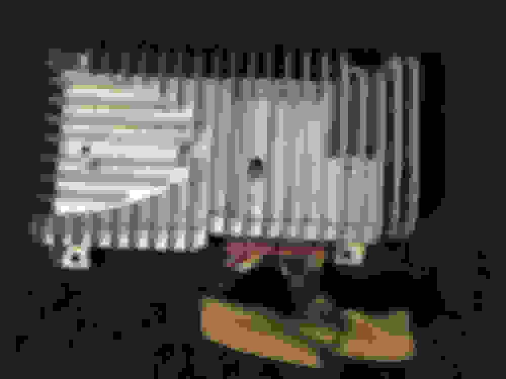
These are the connectors I mean -the audio input connector on the right in this photo of the Bose amp I'd need M plug sides as well as F socket side.....
I will work on this. I think there are standard connectors. I remember something like this for my motorcycle. It's going to be tricky to find out which one it is though.
I will work on this. I think there are standard connectors. I remember something like this for my motorcycle. It's going to be tricky to find out which one it is though.
Wait... I just bought a used Bose amplifier, comes with a chunk of both harnesses so has both sides of the connector I want, $75 incl. shipping. That ought to do it for my needs.
I'll post pictures of the insides of this amp as well as some analysis if I can do some (like maybe some amplifier power measurements....) and I'll poke around in there to see if I can find where they are setting that EQ. Seems unlikely that one could modify this... but you never know, maybe they have some resistor networks that plug in or something like that for the EQ... but seems unlikely. It's probably all SMD parts on a board, in which case there's be no way really to try and figure out where the EQ determining parts are, short of full-on reverse engineering. Which is too much work.
I bought the amplifier pictured above off eBay because I wanted the connectors.
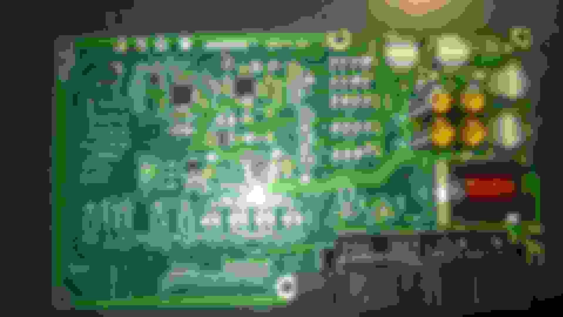
I took the amp apart and this is what is inside:
This is the only board in the Bose "main amp." You can see there's a switching power supply there, transformer and filter caps are there. And there are four big-ish IC's near the power supply with white silicone thermal paste on them. When the board in in place in the metal chassis, these ICs are pressed against areas of the casting that are machined flat, this is how these chips are heat-sunk. Here are the areas in the underside of the cast chassis case that mate against these chips to provide heat sinking, you can see the silicone paste here too.
I am guessing that each of those four chips is a stereo amplifier; outputs from these seem to be routed through a bunch of SMD chokes there to the left of the amplifier ICs, so it's possible - even likely- that these ICs are all "Class D" switchmode amplifiers.
There is 12 volts coming through the wiring harness from the battery through two wires, each supplying power from the battery through a 15 amp fuse. The wires themselves each appear to be 16 ga. in size.... this is consistent with 12 volt ampacity ratings, a 16 ga wire 12 feet in length or so should safely be able to carry 15 amps. I'm guessing there is never 15 amps running through these leads, let's assume 10 amps max. So, that's a total of 20 amps at 12 volts- really it's closer to 14 volts when the car is running - and 20 amps at 14 volts is 280 watts, so assuming typical Class D amplifier real-world efficiency of about 85%, and assuming the other electronics in here take maybe 20 watts, and assuming the DC-DC upconverter is 90% efficient - that means there's about a 200 watt maximum for the total output of these amplifiers. There's 4 amplifier chips, likely each is stereo- so 25 watts a channel seems realistic. Maybe the front 10 inch woofers each are driven with two bridged channels for 50 watts.
So, it could be something like this-
AMP1 -bridged - left front woofer 50 watts
AMP2 -bridged - right front woofer 50 watts
AMP3 - left and right front mid/tweeters 25 watts ea
AMP4 - left and right rear speakers 25 watts ea
Must be another amp in there someplace for the center speaker! If you look at the circuit board, you do see what looks like another amp chip - without any heatsinking except it's tab which seems soldered to the board's ground plane- that could be a smallish amplifier- 10 watts? 20? - for the center.
These are all guesses, and it's possible that these amplifiers put out more than my guesses here, but it could not be a LOT more, given the amount of DC power available to this board.
OK, so, amplifiers, all seems straightforward. Not a TON of power, but then the drivers are all rather efficient and so this is enough power to play pretty loud. (Remember that sound perceived loudness and amplifier power have a logarithmic relationship - in order to double the perceived loudness you need TEN TIMES the power... so if we have a total of 200 watts here, you'd need 2000 watts to double the maximum volume level before clipping... clearly not all that practical in a mass-market car, even a premium one)
But after looking at these amplifiers, we see there is still a LOT of circuitry on this board- in fact there's a crystal, which implies a digital clock for some purpose - DSP maybe? The rest of the stuff on this board could be the Bose crossovers and EQ in DSP form. Who know what else Bose is doing there in the digital domain- image shaping? Bass power level limiting? Dynamic range compression? Anything is possible.
I thought of putting this amplifier on my bench and measuring the power output from the various channels, and certainly that could be done. Just seems like too much work, though.... and I have enough work ahead of me just de-soldering that connector from the PCB so I have a male and female set to use to connect my Mini-DSP's into the signal path between the A/V Head Unit and the Bose amp in the trunk of my G37.
If I do take the time to test some of the channels of amplification here, I will post the results.
AMP1 -bridged - left front woofer 50 watts
AMP2 -bridged - right front woofer 50 watts
AMP3 - left and right front mid/tweeters 25 watts ea
AMP4 - left and right rear speakers 25 watts ea
Must be another amp in there someplace for the center speaker! If you look at the circuit board, you do see what looks like another amp chip - without any heatsinking except it's tab which seems soldered to the board's ground plane- that could be a smallish amplifier- 10 watts? 20? - for the center.
The front door subs get 75 watts each. The rear deck subs get 35 each. Each of the mid range, front and rear, including the center channel get 15 each. The fronts are in parallel with the tweeters so they share the power. I told you I had this info a while ago. I just called Bose Auto haha.
Where is that amp located in the car? And what kind of DSP do you think this utilizes? It would be awesome if we could just rip out this amp and connect to the factory speaker locations through a harness.
I still want to come up with some kind of adapter to run aftermarket (shallow mount) 10s in the doors.
Both are located in the trunk to the left of the spare tire.
 06-09-2017, 10:47 AM


 will try that experiment when i get some time i guess ...
 ")