Notices
Body Interior Exterior Lighting

Need help!! Diy turn as tail diode dynamics

Thread Tools
 
Search this Thread
 
Old 12-21-2015, 09:19 PM
  #91  
RxRyanM
Registered Member
 
RxRyanM's Avatar
 
Join Date: Jul 2013
Location: Lex, KY
Posts: 219
Received 43 Likes on 35 Posts
Out of curiosity for when I get around to this (warmer and no rain), where did y'all secure your resistors?
Old 12-23-2015, 03:13 AM
  #92  
Arrogant
Registered User
 
Arrogant's Avatar
 
Join Date: Aug 2014
Posts: 173
Received 13 Likes on 12 Posts
Originally Posted by ocie
I would skip the red plastic splices and merge the wires.

Scroll down and look at the picture with the Facebook like thumbs up to see a picture of what i'm talking about: How To Install 50W 6-Ohm Load Resistor For LED Turn Signal Lights

Use your wire stripper to expose the copper wire on the green turn signal wire and the green w/yellow stripe wire. Then, strip both resistor wires so you have a half-inch or so exposed on each, then wrap the ends around the exposed wire on the green and green w/yellow stripe wires. It doesn't matter which side of the resistor you connect to the green and green w/yellow stripes.

Then test your brake lights and if the connection is good, wrap electrical tape around the merge you just did and you're good to go.
Ok, I realized I am still lost. I understand I need to merge now, but is there a diagram or quick instructions of where the resistor is wired in? For instance does the resistor go in between the car and the module or between the light and the module? I thought the resistor was connected to a black ground too? A step by step would be great if it's not too annoyijg. The module seems easy throw the resistor in and I'm confused as hell.
Old 12-23-2015, 07:04 PM
  #93  
RxRyanM
Registered Member
 
RxRyanM's Avatar
 
Join Date: Jul 2013
Location: Lex, KY
Posts: 219
Received 43 Likes on 35 Posts
Originally Posted by Arrogant
Ok, I realized I am still lost. I understand I need to merge now, but is there a diagram or quick instructions of where the resistor is wired in? For instance does the resistor go in between the car and the module or between the light and the module? I thought the resistor was connected to a black ground too? A step by step would be great if it's not too annoyijg. The module seems easy throw the resistor in and I'm confused as hell.
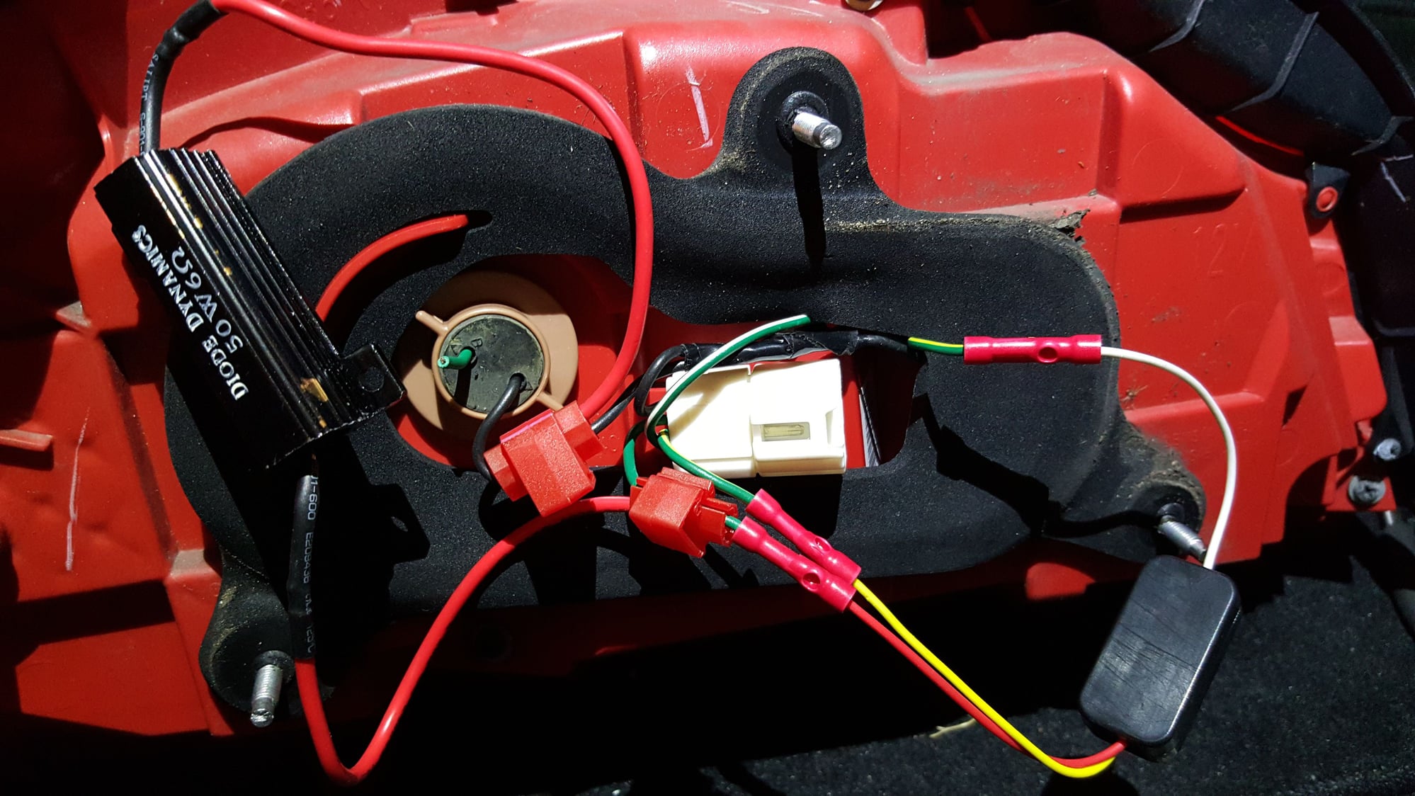
Looks like it's in front of the module on this pic I snagged from a YouTube vid posted by a fellow member.


Old 12-24-2015, 02:23 PM
  #94  
2GoRNot2G
Premier Member

iTrader: (5)
 
2GoRNot2G's Avatar
 
Join Date: Dec 2008
Location: SoCal
Posts: 2,360
Received 399 Likes on 330 Posts
Originally Posted by Arrogant
Ok, I realized I am still lost. I understand I need to merge now, but is there a diagram or quick instructions of where the resistor is wired in? For instance does the resistor go in between the car and the module or between the light and the module? I thought the resistor was connected to a black ground too? A step by step would be great if it's not too annoyijg. The module seems easy throw the resistor in and I'm confused as hell.
The resistor connects between the harness side of the wire you cut that went to the factory turn signal bulb (it's the green wire, but not the green/yellow wire) and the black ground wire.

Here's a video of mine installed. I opted to keep the factory turn signal bulbs installed and have since replaced those with LED bulbs which makes them really pop.

http://vid71.photobucket.com/albums/...psb1uce9bz.mp4

Old 12-27-2015, 04:07 PM
  #95  
Dreamerzcc
Registered User
 
Dreamerzcc's Avatar
 
Join Date: Mar 2015
Posts: 163
Received 8 Likes on 8 Posts
Well I got mine working after having to make sure the resistors had a better connection. Loving the look. Already had a G owner ask me how it was done.
Old 12-27-2015, 04:35 PM
  #96  
Mattlorentzoe
Premier Member

iTrader: (4)
 
Mattlorentzoe's Avatar
 
Join Date: Jun 2015
Location: Gwinnett County, Georgia
Posts: 773
Received 156 Likes on 119 Posts
Yes just got mine in today also. I love it! Can't beat the price!
Old 12-29-2015, 02:15 PM
  #97  
Dreamerzcc
Registered User
 
Dreamerzcc's Avatar
 
Join Date: Mar 2015
Posts: 163
Received 8 Likes on 8 Posts
Originally Posted by RxRyanM
Looks like it's in front of the module on this pic I snagged from a YouTube vid posted by a fellow member.


It doesn't matter if its in front or behind the module. Just where you have the space. One side of mine is in front and the other side is behind the module. I did not merge but shaved the lining down until I was able to see the wires and then used the connectors and all was good.
Old 12-29-2015, 02:30 PM
  #98  
mrig37
Registered User
 
mrig37's Avatar
 
Join Date: Nov 2015
Posts: 149
Received 12 Likes on 10 Posts
Got mine done about 4 days ago and they amazing best mod for the price
Old 12-29-2015, 04:33 PM
  #99  
JSolo
Just say no!!!!!
iTrader: (14)
 
JSolo's Avatar
 
Join Date: Oct 2011
Location: People's Republic of IL
Posts: 6,105
Received 588 Likes on 492 Posts
Soldered connections or bust! Those wire taps is just asking for trouble down the road same with the crimp connectors. The right way is to solder and seal off with heatshrink tubing.
Old 12-31-2015, 08:00 AM
  #100  
Dreamerzcc
Registered User
 
Dreamerzcc's Avatar
 
Join Date: Mar 2015
Posts: 163
Received 8 Likes on 8 Posts
Originally Posted by Jsolo
Soldered connections or bust! Those wire taps is just asking for trouble down the road same with the crimp connectors. The right way is to solder and seal off with heatshrink tubing.
I have used crimp connectors in 5 vehicles with no problems ever. Easier to undo also.
Old 01-22-2016, 01:35 AM
  #101  
JohnsG37x
Registered User
 
JohnsG37x's Avatar
 
Join Date: Apr 2009
Location: PA
Posts: 137
Received 6 Likes on 5 Posts
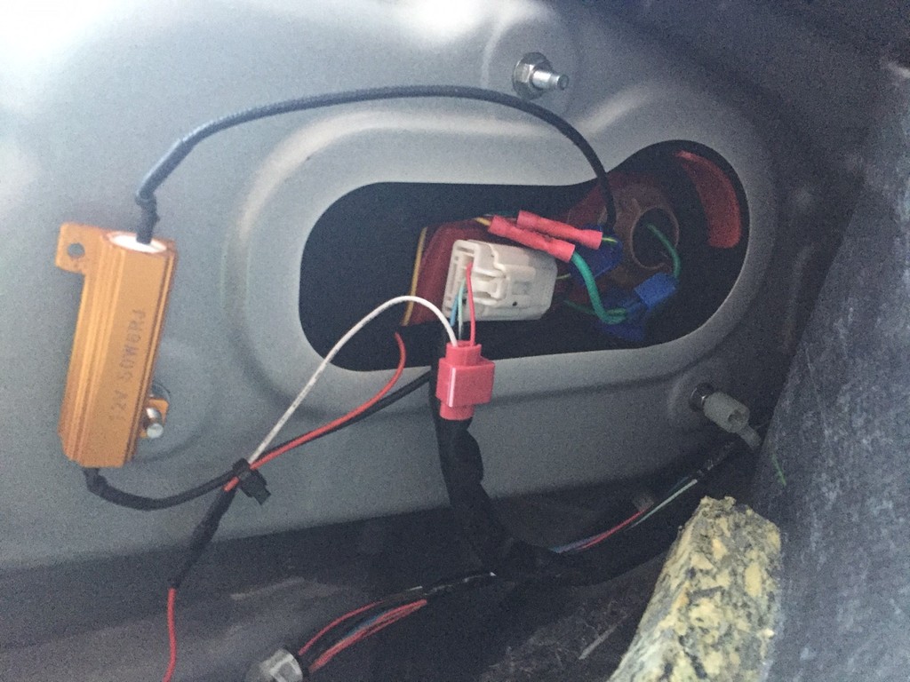
Installed my tail as turn diy kit as well. love this cheap mod! here's another picture of the wiring with a resistor in case anyone is still confused.

The following users liked this post:
Diode Dynamics (01-22-2016)
Old 02-05-2016, 01:38 AM
  #102  
dust10
Registered Member
 
dust10's Avatar
 
Join Date: Feb 2016
Posts: 3
Received 0 Likes on 0 Posts
Any suggestions on where to mount the resistor?
Old 02-05-2016, 12:42 PM
  #103  
Diode Dynamics
Former Sponsor
iTrader: (11)
 
Diode Dynamics's Avatar
 
Join Date: Jul 2011
Location: St. Louis, Missouri
Posts: 2,106
Received 141 Likes on 117 Posts
Originally Posted by dust10
Any suggestions on where to mount the resistor?
Preferably on a metal surface, away from soft plastics or rubber

They will generate heat when the turn signal is in use

Nick C.
Old 02-05-2016, 02:11 PM
  #104  
2GoRNot2G
Premier Member

iTrader: (5)
 
2GoRNot2G's Avatar
 
Join Date: Dec 2008
Location: SoCal
Posts: 2,360
Received 399 Likes on 330 Posts
Originally Posted by dust10
Any suggestions on where to mount the resistor?

I mounted mine directly to the inner most mounting stud for the tail light housing. This keeps the resistor mounted to metal but also basically keeps it "floating" in open air space.


Name:  IMG_3948_zpsvexcm5ug.jpg
Views: 358
Size:  201.7 KB
Old 02-05-2016, 11:07 PM
  #105  
dust10
Registered Member
 
dust10's Avatar
 
Join Date: Feb 2016
Posts: 3
Received 0 Likes on 0 Posts
I Noticed that my front and rear turn signals flash in sync until I hit the brake and then they flash out of sync. Once I release the brake they start flashing synchronously again. Is this normal or did I maybe get some wires crossed?


Quick Reply: Need help!! Diy turn as tail diode dynamics


All times are GMT -4. The time now is 02:17 AM.