DIY: Front lower control arms
 04-24-2016, 12:46 PM
#1
Registered Member
Thread Starter

Front lower control arms
Tools needed
Reasons to replace lower control arm (aka: transverse link, LCA)
Procedure
Acknowledgements and references
- 17mm socket
- 19mm socket
- 22mm socket
- 17mm wrench
- 19mm wrench x2 recommended
- ratchet (x2 optional)
- 2' breaker bar
- impact gun (optional)
- needle nose pliers
- hack saw
- pry bar (indexing pry bar)
- torque wrench
Reasons to replace lower control arm (aka: transverse link, LCA)
- Play in ball joint (spec is 0mm of axial play). Note: Two dealers highlighted the play without me asking about it and one even showed me the play. These were highlighted over the past year or so. At the onset of this job I was not sure if it would progress to be much worse. Once removed, my original LCAs had the tiniest amount of play (a fraction of a millimeter). At the level of play I found I would in no way be concerned about safety. In hindsight, there is a 50% probability I would replace them if shown a similar amount of play. I cannot say I noticed anything immediate symptoms while driving, my front tires were wearing evenly, and the car handled great.)
- Bent/cracked
- Worn bushings
- Upgrading bushings
Procedure
- Lift car, place all four corners on jack stands, remove lug nuts and wheels.
- Remove undercover (recommended by service manual). I did not do this as my undercover was not in the way.
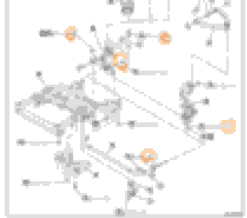
- Remove the shock absorber. Use a 17mm socket (blue arrow) and 17mm wrench (red arrow) to undo the end link from the front sway bar.

Undo the 19mm nut (orange circle) on holding the shock absorber to the control arm. A 19mm wrench (pink arrow) is needed to loosen the nut and prevent the end link from spinning in the ball joint. Be careful not to damage the rubber boot on the end link. The wrench can be wedged again the knuckle or lower control arm. This nut is torqued to 120 ft-lb, bring out the breaker bars.

- Remove the tie rod end (recommended by the service manual). I did not do this. It may have made getting the new lower control arm in easier. I like to live dangerously... I mean lazily and undo as little as possible.
- Remove lower control arm from knuckle. Pull or push the cotter pin out. This didn't go so well in my case. Using a hack saw, I cut the cotter pin flush with the stud and then used a 22mm socket to remove the nut.
When turning the nut you may run into a situation in which the ball joint is turning and the nut is not loosening. To prevent the ball joint from spinning, apply some pressure to the ball joint to wedge it into its seat. I did this using a crow bar levered on the brake caliper nut and the top of the control arm's ball joint. The position of the crow bar is shown below.

Once the 22mm nut is removed, the knuckle can be pushed down and off the ball joint stud.
There is a black conical seat between the ball joint and the knuckle. Sometimes this will stick to the knuckle and other times it will stick to the ball joint (the latter was the case for both of mine). I replaced both of these, however the old ones showed no wear.
- Remove the three remaining lower control arm mounting bolts and nuts. The rear impact bushing can be removed by loosening the two 17mm nuts directly below the mount from beneath the car. These nuts are very accessible and can be cracked loose easily with a 2' breaker bar. Once loose, you will need to the hold the bolt heads from the top of the car, a second ratchet worked well for this. The nuts on are visible in this picture (note: left side of car is pictured, while most other pics show the right side).

On the front bushing, hold the head of the stud with a 19mm wrench (front, green arrow). Use a 19mm wrench to loosen the nut on the rear (red semicircle). There is a tab on the head of the stud to limit rotation, I would not trust it. Once the nut is removed, remove the stud. I tapped the stud to get it started, and then pried it out from the front using an indexing pry bar

All three nuts in this step are not meant to be reused as they have locking tabs. Order new ones from the dealer and replace during reassembly.
At this point the lower control arm didn't fall out for me. I had to wiggle it out and play tetris. I suspect it would be marginally easier with the tie rod end disconnected.
- To install the new lower control arm you'll have to play tetris again. It is a little harder to get it back in than it was to get it out. The rear impact bushing had a piece of stamped steel over it, put this on before maneuvering the new lower control arm into place. I found it easiest to get front bushing half into its bracket first, then get the shock absorber into the mount on the control arm, finally wiggle the front bushing all the way in, line up the holes and push the stud in. At this point the rear impact bushing will into sit flush against the front subframe. With some wiggle you can draw it in using it's bolts and nuts.
The remainder of the install is the reverse of the removal. Do not forget to reinstall the black conical seat between the ball joint and knuckle. Be mindful of the rubber boot on the ball joint, any damage to the boot will shorten the life.
The upper end link/shock absorber nut should be tightened with the wheels on the ground. This was not possible for me. As the next best solution, I used a floor jack to lift the lower control arm up and then tightened and torqued the bolt.
- Torque all the bolts removed.


Acknowledgements and references
- Thanks to my buddy Dan for his help, tools, and garage.
- The factory service manual.
- The following links had some pics and some details of the process:
SPL lower control arm bushings
The Complete SPL Front Suspension

The following 8 users liked this post by Dough1397:
Baadnewsburr (04-24-2016),
flipmode007 (03-06-2020),
G10 (11-14-2018),
JaE35 (05-07-2018),
MStrike (08-15-2021),
and 3 others liked this post.


 09-12-2017, 09:15 PM
#4
Registered Member
Thread Starter
The awd (X) models have separate mounts for the strut and sway bar onto the lower control arm. The rear inner mount for the lower control arm is also attached differently. Given these differences, I don't think this DIY would apply perfectly to an awd (X) model.
08-13-2019, 10:08 AM
#5
Registered Member
Thread Starter
I have not yet had to replace my front upper control arms. If and when I do, I�ll be sure to create a similar DIY if one does not exist by then.
08-13-2019, 03:33 PM
#6


This https://www.myg37.com/forums/d-i-y-i...er-adjust.html thread has been on this site for over 10 years...its on the first page of stickied threads in the DIY section...specifically related to the SPC FUCAs

Thread
Thread Starter
Forum
Replies
Last Post
Dough1397
Brakes & Suspension
2
06-25-2019 01:10 AM
philttz
Brakes & Suspension
4
05-24-2019 10:30 AM