When you click on links to various merchants on this site and make a purchase, this can result in this site earning a commission. Affiliate programs and affiliations include, but are not limited to, the eBay Partner Network.
Did not build my own, just bought it from Stillen ($99). Figured it wasnt worth my time to build it.
Took 1-hour but was following the Stillen instructions and it didnt feel quite right. So resorted to THIS DIY.
Gotta thank AZg37 for taking the time to do the writeup.
Results: agree with most that the shift are much quicker than ever before. Upshifts when pressing on the throttle seem to shift quicker, Manual mode shifting is improved as well. Overall, I'm starting to like this car .vs. curse the car because of how sloppy it shifted. Well worth the time/money to install this if you have a 7AT.
This is a copy of something I posted on the DIY sticky for the grounding cables. Putting it here because this thread is more recent.
Connecting an additional cable from the battery negative terminal directly to the chassis bypasses the battery current sensor, which can impact the power generation voltage variable control system, possibly leading to improper battery charging.
If this causes the alternator to charge too often, it can cause battery over-charging, premature alternator failure and decreased fuel efficiency.
It seems to me like the additional ground to the negative terminal would cause the battery current sensor to see less of the current, making it think there was less battery use, causing it to under-charge. Not only is a weak charged battery an issue for multiple reasons, but on my 'vert could impact the top operation which is very sensitive to battery voltage.
Like many current sensors, the battery current sensor appears to be a "ring" that just sits around the factory ground cable. The factory ground cable seems very thin and the battery current sensor appears to have plenty of room to accept a much thicker cable.
Has anyone tried to replace the factory ground cable from the negative battery terminal to the chassis by running a thicker gauge ground cable through the battery current sensor?
I wonder if the decreased space between the sensor and a thicker cable would cause the sensor to incorrectly sense what it thought was a higher current, causing the alternator to run too much?
Could this be why I had to replace the battery on my 5 year old car the other day? If so, I'm removing that grounding cable to the battery asap.
Just a follow up. Removed the connection to the battery and have noticed no negative effects. Shifts are still snappy and it's been a month. Time will tell whether I have additional battery problems.
Last edited by gord27; 05-10-2016 at 09:52 PM.
Reason: Follow up
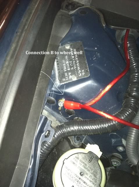
Apologies that my first post has to be in this thread. I own a 2013 G37S sedan. I've been able to follow these instructions but I noticed that I am missing the following grounding point (point B in the OP). As you can see, it's covered up by this soft material that feels like insulation. You can also see it on the right hand side of the 2nd picture, in between the 2 rubber grommets.
I decided to ground point B to the washer fluid reservoir bracket instead, but I'm not sure if it is grounded to the chassis. Can anyone confirm? I have not been able to notice any difference in how the car shifts (it is a 7AT), which leads me to suspect that I have configured the wires incorrectly.
Comparing the two pics (yours and the OP) it appears there is a removable cap where the nut is. Have you tried popping that off?
Also, I believe, even if you're missing one connection it should still make a noticeable difference. For example, I removed the battery connection and noticed no ill effects.
It makes your brain efficiency (placebo effect) grow by 18%. It helps you be ok with the fact that you bought a poorly designed 7at that will have problems or harsh shifting at as early as 30,000 miles - the life of the car.
In summary it doesn't do much. The principles of how electrics work states that it would help. Help by how much? That's the question up for debate. Worth the diy price? Yes.
Worth the Stillen price, No, in my opinon.
better return path for electric current to the battery - less resistance = less loss.
as lorentzoe45 stated above, for $15 - $20 (or less if you have the tools and material needed already), sure why not. doesn't take long to do, and pretty easy.
for the ridiculous prices of some of the pre-made kits? no.
Hey all, my first post on here! I am prepping my kit right now as we speak. Through a ton of research, through here and personal experiences, this should end up being one of the most useful mods on your 7AT imo. If you choose to do nothing but 1 mod, make it this one. An update to follow post-install and testing for a bit!
Noticeable shifting differences yes. Used to keep the car in DS sport prior and I would notice the gear changes when driving local ~25-40 mph. After this and DS mode, smoother shifting that really isn't as noticeable unless you listen to your exhaust note.
Also my HID headlights "charge" up a bit quicker, maybe due to the gas heating up much faster. Very impressed at this write up, great mod!
This guide will allow you to make your own grounding kit. These instructions will work for 2nd Gen G35 sedan, 08-XX G37 coupes, 09-XX G37 Sedans and 350/370 Z's. Please note the layouts may not be 100% identical between models, but you should be able to adjust and make these instructions work. By following these instructions, you will have every thing you need to make and install your own grounding kit that will help with car audio quality, as well as firm up those transmission shifts and fix lag in 5AT and 7AT coupes and sedans.
Items you will need:
12 ft. of 8 gauge oxygen free copper cable
6 individual 8 gauge ring terminals
3 individual 4 gauge ring terminals
Crimping tool and wire stripper
some zip ties for neatness, if you desire (I didn't use any)
Please note that all measurements in the photos are taken from the crimping point of the terminals and not from the end of the terminals themselves. The total amount of wiring used is 136 inches, so having 12 feet will allow you 8 inches of extra wiring to make sure you have enough.
Better to be slightly long in measuring than to have wires that are too short!!!
The kit is broken down into 3 wires: the drivers side wire, passenger side wire, and single connecting cable.
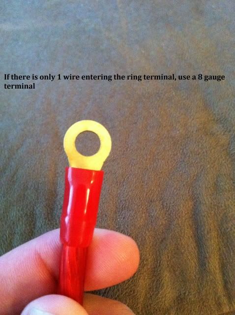
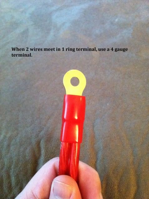
You'll note that there are 2 different sizes in ring terminals. This is explained here:
Use these next photo's to identify the length of each cable and connection, as well as which terminal goes to which connection point. There is a total of 9 connections, labeled A,B,C,D,E,F,G,H,I. You can also choose to go off course and mount additional wires to anywhere you want a strong ground signal. Some choose to add throttle body grounds, and some ground the ECU directly. It's all up to you! This instructions are for just a basic grounding kit that gets the job done!
MAKING THE WIRES
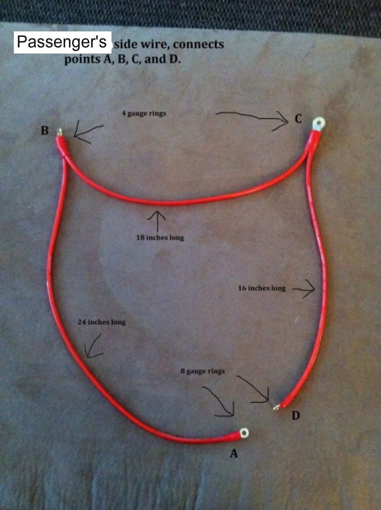
Passenger's side wire lengths and construction:
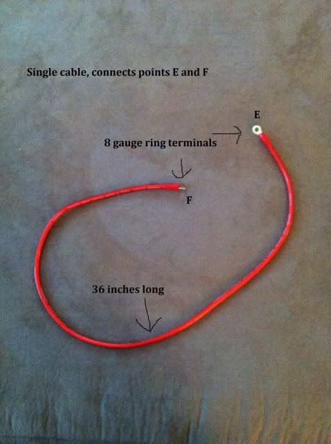
Connecting Cable:
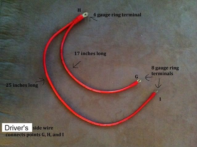
Driver's side cable:
After you construct your 3 cables in the specified lengths, follow these installation instructions to enjoy your creation!
INSTALLATION:
Items you will need:
Ratchet, 10mm socket, extension if desired, 10mm wrench, 12mm socket.
Step 1. Detach the negative battery terminal from the battery.
Step 2. Remove the engine shroud and set it aside.
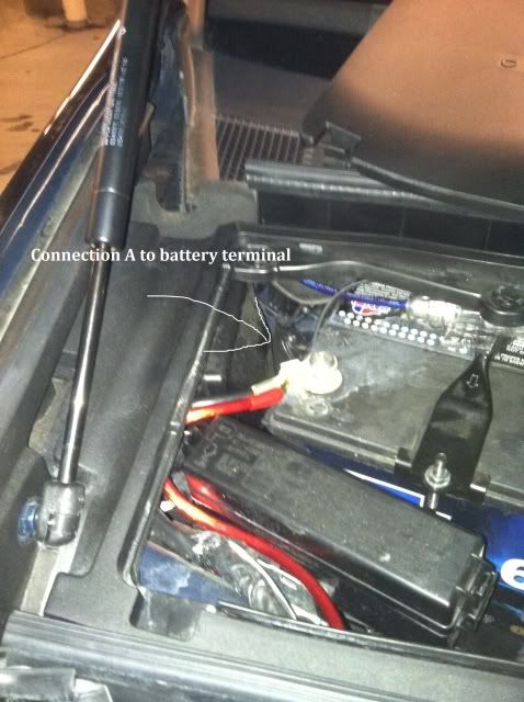
Step 3. Attach connection terminal A on the passenger side wire to the negative battery terminal. You can simply force the wire through the existing wire loom leading into the battery box. Wait to connect the wire to the batter until the end of the install.
Step 4. Attach connection terminal B to the passenger's side wheel well bolt where there is already wires connected.
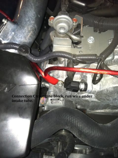
Step 5. Attach connection terminal C to the engine block corner next to intake. Make sure to run the wires under the intake tube.
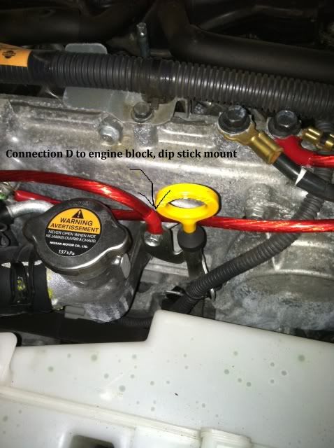
Step 6. Attach connection terminal D to the front of the engine using the dipstick mount. Passenger side wire is now complete!
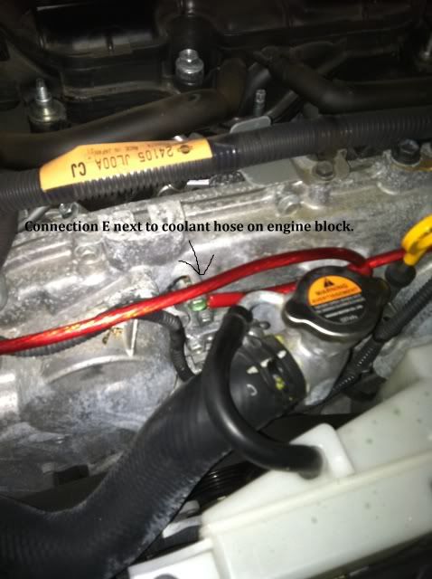
Step 7. Using the single connecting cable, attach connection terminal E to the engine block bolt behind the coolant hose:
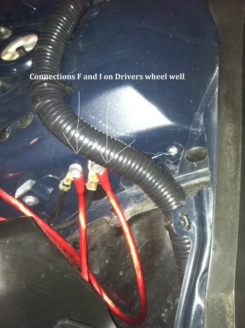
Step 8. Connect terminal F to the bolt on the drivers side wheel well, making sure to tuck the wire under the driver's side intake tube. Single cable is now complete!
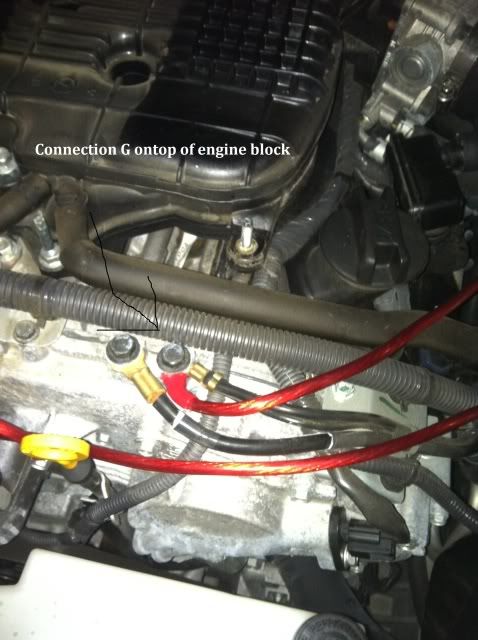
Step 9. Using the Driver's side cable, attach connection terminal G to the top of the engine block where there are wires already connected:
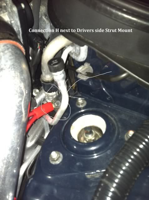
Step 10. Attach connection terminal H to the mount on the wheel well next to the driver's side strut, across from the intake/throttle body. Make sure to run the wires under the intake tube.
Step 11. Attach connection terminal I next to connection F on the drivers side wheel well where there are already wires grounded. This completes the driver's side wire!!
Step 12. Connect connection A from the passenger side wire to the battery terminal, make sure all connections on all wires are tight, and then replace battery box cover.
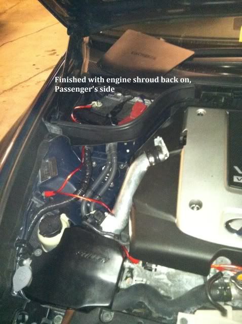
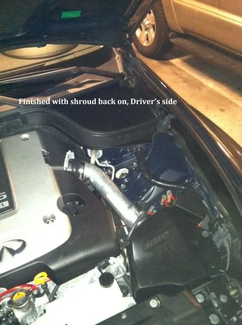
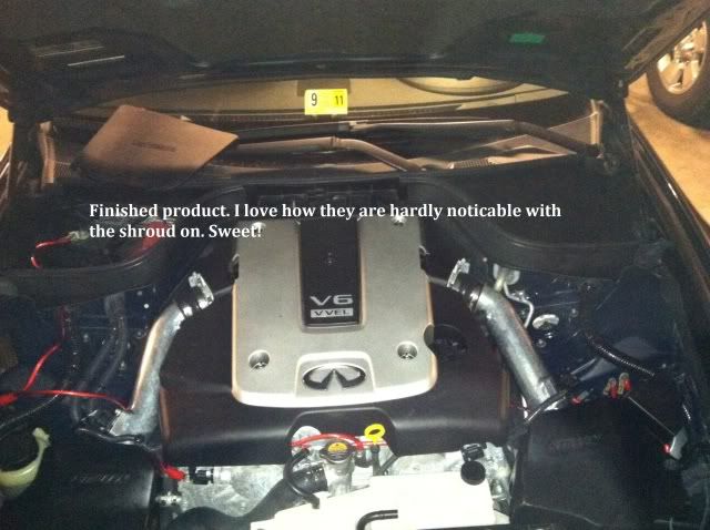
Step 13. Replace engine shroud cover, make sure all wires are tucked, secure, and not in the way of anything.
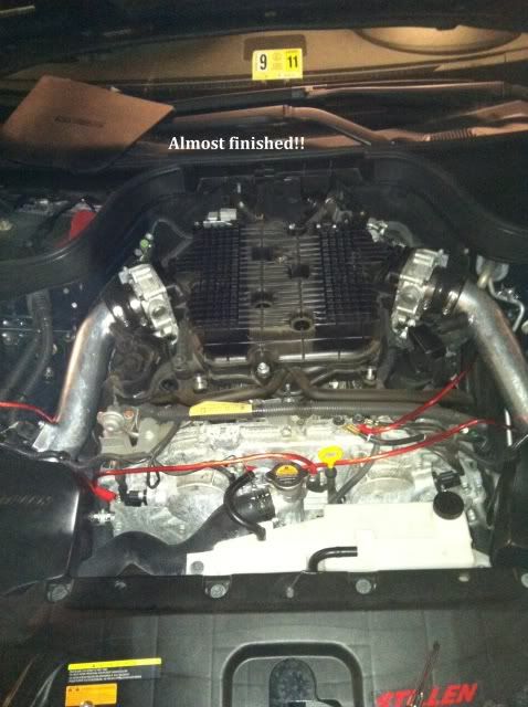
YOUR JOBS DONE, TIME TO ENJOY TRANSMISSION AND AUDIO IMPROVEMENTS!!!!!
RESULTS
Most owners notice an immediate improvement in audio sound. Audio levels seem louder. I noticed this first hand and was very impressed. Owners also report improvements in Automatic transmission shifting. The lag between shifts in DS mode are dramatically improved, and shifts are firm and tight. It's also an added bonus that the wires look pretty cool, but if you don't want them to be an eye sore, tuck and zip-tie them away.
Oh yea, just got my G37 coupe and will be doing this mod this weekend. Awesome DIY
Just did this yesterday on my car. Nice mod and nice write-up. The only thing is, I noticed it works out a little better if you swap I and G grounding points. Also, a spade connector might work a little better for the battery connection. I was able to do this mod for $21 and some change 😀. Money well spent
I snapped the heads off the bolts for connections B and F, and the screw half of the bolt is still in the hole on each.
Any tips on removing them? I tried cobalt "Speedout" and it kind of cut into the shaft but didnt get in far enough to dig it out.
Thanks
Is there any bolt sticking out to the point you can get a set of pliers around it? If not, I'd get some WD-40 to grease it up then drill a hole in the middle of the bolt. Thread your extractor in the drilled hole and if you feel like you can, use the drill to grab onto the extractor and see if you can SLOWLY back the broken bolt out. Good luck
I've done something similar, but nowhere as involved. I didn't run all of the wires. I just took sandpaper and removed the paint at the three (B,F &I) fender locations noted in the first link to get a true metal to metal contact (added dielectric grease to help prevent rusting here as well) and then just ran one 4ga grounding wire from the Battery Neg to one of the bolts on the intake manifold that already had a ground wire (I think it was location E). I didn't feel the need for adding all of the wires as described as I verified with my Fluke Ohm Meter that they were already (electrically speaking) connected with 1 Ohm or less resistance. By only doing what I did, I had an Ohm reading of 0.7 when I measured from the Neg on the battery to locations F & I.
I do plan on going back and relocating my mounting point at the battery to shift it over to what scarguy055 mentioned in post #167. I just didn't have the time to remove all that I needed to remove to be able to get my big hands in there when I did my install.
 01-12-2016, 09:25 PM


 Hey all, my first post on here! I am prepping my kit right now as we speak. Through a ton of research, through here and personal experiences, this should end up being one of the most useful mods on your 7AT imo. If you choose to do nothing but 1 mod, make it this one. An update to follow post-install and testing for a bit!