Ape's IPL build (How Nissan should have done it)
 01-09-2017, 12:55 AM
#61

I need to go back and double check the weight of various OEM components vs. their aftermarket counterparts in the suspension dept. but off the top of my head:
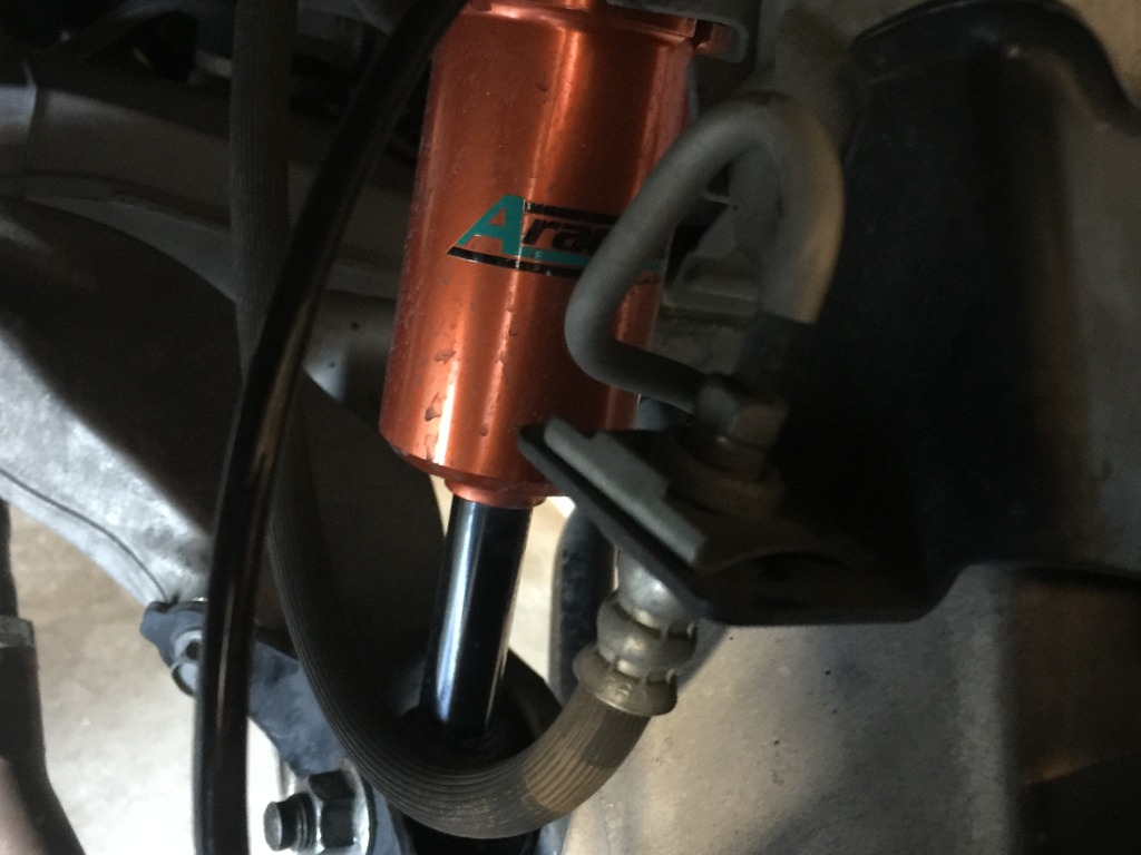
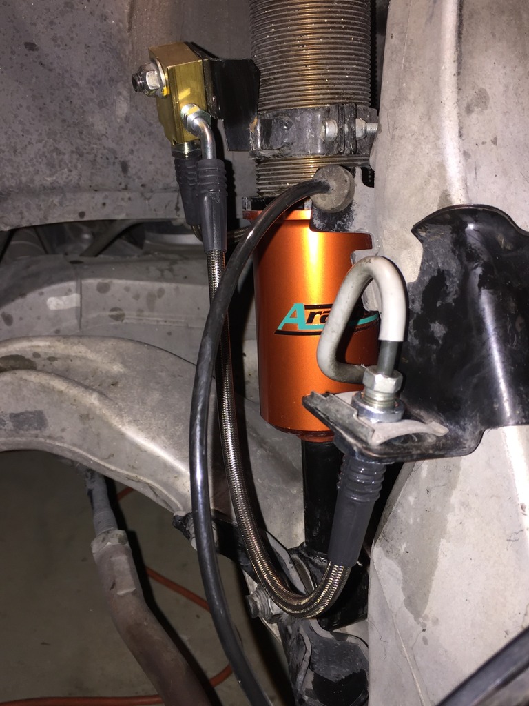
Aragosta fronts, 5 pounds lighter than stock, each side
Aragosta rears, 1 pound heavier, each side
SPC front camber arms, 1 pound heavier each side
SPL rear camber arms, a wash.
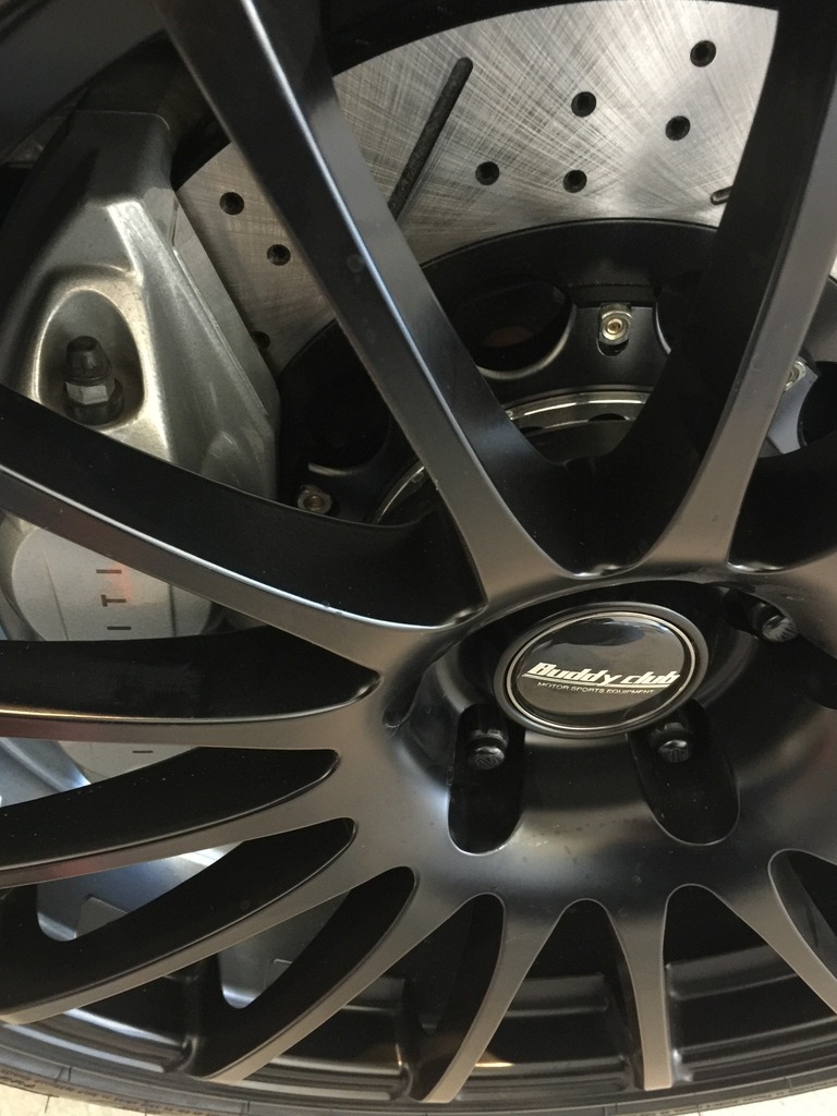
Front Buddy Club/Michelin combo, 2 pounds lighter than stock each side
Rear Buddy Club/Michelin combo, 4 pounds lighter per side
I have yet to add in the Z-1 two-piece rotors front and rear which'll save 10 pounds front, per side, and four pounds rear, each side.
Total weight loss;
-16 pounds for each front wheel, 32 pounds total.
-7 pounds for each rear wheel, 14 pounds total.
I'm going to revisit my alignment and go from -.04 camber up front to -.08 and then decrease the camber in the rear from -1.6 to -1.3 for more stability on acceleration and acceleration while cornering.
I'm also considering aftermarket traction arms with bushings that are more stiff than OEM.
Aragosta fronts, 5 pounds lighter than stock, each side
Aragosta rears, 1 pound heavier, each side
SPC front camber arms, 1 pound heavier each side
SPL rear camber arms, a wash.
Front Buddy Club/Michelin combo, 2 pounds lighter than stock each side
Rear Buddy Club/Michelin combo, 4 pounds lighter per side
I have yet to add in the Z-1 two-piece rotors front and rear which'll save 10 pounds front, per side, and four pounds rear, each side.
Total weight loss;
-16 pounds for each front wheel, 32 pounds total.
-7 pounds for each rear wheel, 14 pounds total.
I'm going to revisit my alignment and go from -.04 camber up front to -.08 and then decrease the camber in the rear from -1.6 to -1.3 for more stability on acceleration and acceleration while cornering.
I'm also considering aftermarket traction arms with bushings that are more stiff than OEM.
Last edited by Ape Factory; 01-09-2017 at 01:00 AM.
 01-09-2017, 01:27 AM
#62
Brakes! The stock Akebono sport setup is pretty good for daily, even aggressive street driving. With the right pads, they work well on the track too.
With that said, I felt, even on the street, there was room for improvement while keeping the daily livability of the vehicle. That means you're able to drive smoothly, work when cold and no squeal. I noticed the stock pads would loose their initial bite and feel in the hot summer months. I wanted something that would work in a wide range of ambient temperatures and weather conditions, namely rain, and make a noticeable improvement in initial bite, modulation and overall braking force.
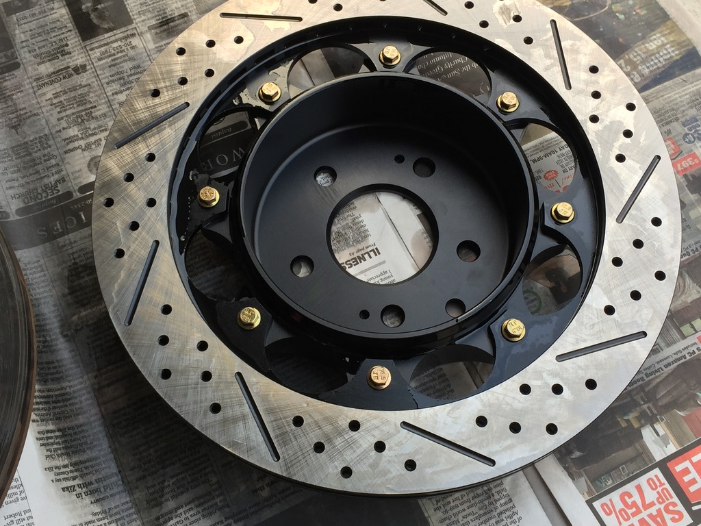
Instead of going with one-piece rotors, I decided two-piece would be a better option, specifically Z1's two-piece setup. They're somewhat reasonable in cost and they save a bunch of unsprung weight. The replacement disks cost less than all of their competitors too. Since they're made with performance in mind, their metal composition is going to be more performance-oriented than your OEM rotor and a lot of the less expensive aftermarket rotors. They'll also cool more quickly due to their hat design which is more open to airflow.
The rear disks also maintain the parking brake feature.
I haven't had much experience with a lot of the modern performance pads so my pad selection is a bit of a guessing game based on reviews. Cost was a consideration and I ended up choosing the Nismo pads which are made by Ferodo.
For brake fluid, I'm going with Motul 5.1 as it flows better through small valves like the ones found in modern ABS systems.
I ordered the Z1 rotors cross drilled and slotted. If I were doing track days, I'd go with solid disks.
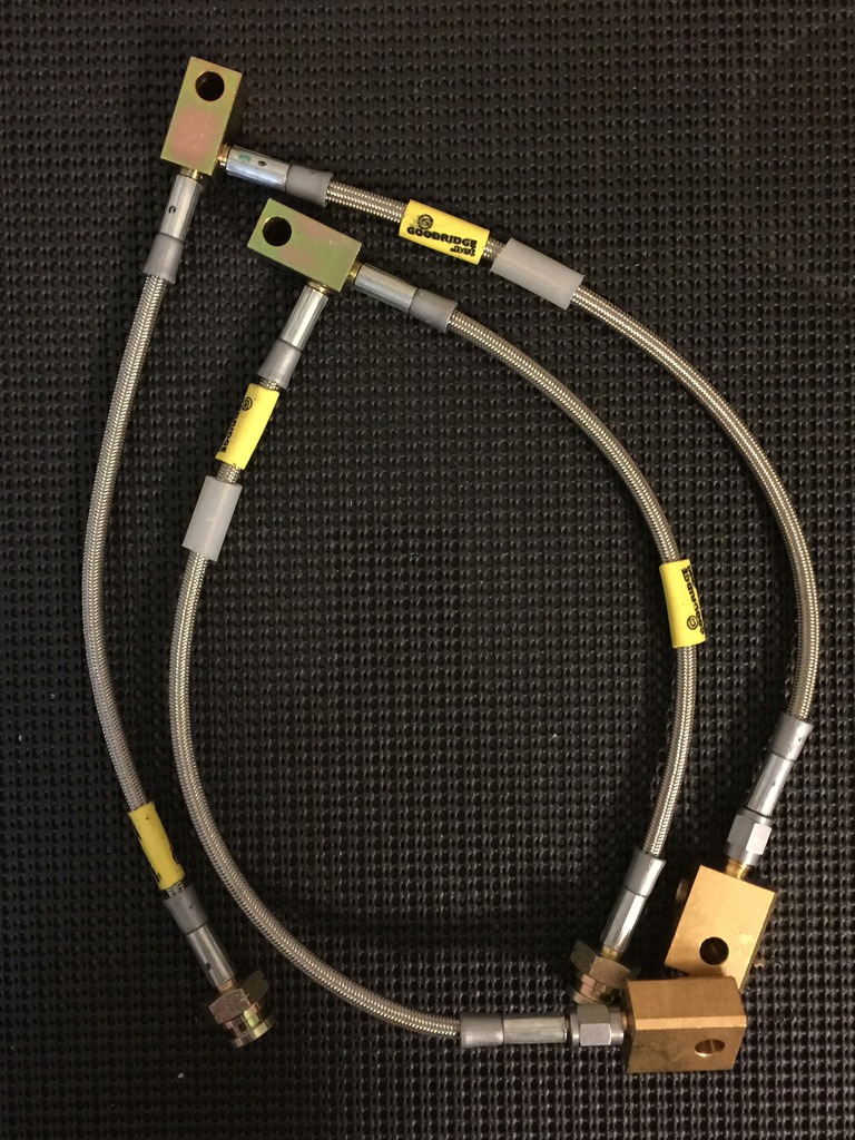
Brake lines. I wanted Goodrich braided lines as they retain the OEM brass block setup, OEM routing and are DOT approved. If you have an S or IPL made prior to 06/2012, the Goodrich kit you'll use is different than if you have a vehicle made after that date.
Pre-06/2012 Goodrich PN 24-5127
Post-06/2012 Goodrich PN 24-5117
I've only seen one shop that lists both part numbers and that's Welcome To Motorsport & The Z Store! Nissan-Datsun 240Z-260Z-280Z-280ZX-300ZX(Z31/Z32)-350Z-370Z Parts! I've searched high and low for a Goodrich catalog with part numbers and I've never found one.
I made the mistake of ordering the pre-06/2012 lines despite the fact I have a 2013 model year. I thought it was an error. It's not.
So what's different? The front lines have one fitting that's different.
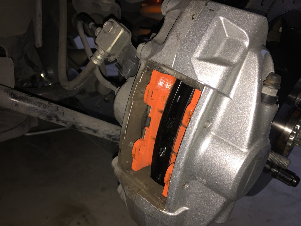
Here's the pre-06/2012 front lines. If you look at the bottom right of the photo, you'll see the lines terminate in a brass block. On the later model years, it's a straight fitting and it eliminates the brass block.
Here's a photo of that portion of the brake line on my car:
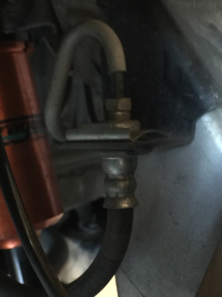
So...I'll have to return the braided lines and get the version for the 06/2012+ years.
I have a power bleeder on the way and as soon as the new lines come in, it's time for a fluid swap.
With that said, I felt, even on the street, there was room for improvement while keeping the daily livability of the vehicle. That means you're able to drive smoothly, work when cold and no squeal. I noticed the stock pads would loose their initial bite and feel in the hot summer months. I wanted something that would work in a wide range of ambient temperatures and weather conditions, namely rain, and make a noticeable improvement in initial bite, modulation and overall braking force.
Instead of going with one-piece rotors, I decided two-piece would be a better option, specifically Z1's two-piece setup. They're somewhat reasonable in cost and they save a bunch of unsprung weight. The replacement disks cost less than all of their competitors too. Since they're made with performance in mind, their metal composition is going to be more performance-oriented than your OEM rotor and a lot of the less expensive aftermarket rotors. They'll also cool more quickly due to their hat design which is more open to airflow.
The rear disks also maintain the parking brake feature.
I haven't had much experience with a lot of the modern performance pads so my pad selection is a bit of a guessing game based on reviews. Cost was a consideration and I ended up choosing the Nismo pads which are made by Ferodo.
For brake fluid, I'm going with Motul 5.1 as it flows better through small valves like the ones found in modern ABS systems.
I ordered the Z1 rotors cross drilled and slotted. If I were doing track days, I'd go with solid disks.
Brake lines. I wanted Goodrich braided lines as they retain the OEM brass block setup, OEM routing and are DOT approved. If you have an S or IPL made prior to 06/2012, the Goodrich kit you'll use is different than if you have a vehicle made after that date.
Pre-06/2012 Goodrich PN 24-5127
Post-06/2012 Goodrich PN 24-5117
I've only seen one shop that lists both part numbers and that's Welcome To Motorsport & The Z Store! Nissan-Datsun 240Z-260Z-280Z-280ZX-300ZX(Z31/Z32)-350Z-370Z Parts! I've searched high and low for a Goodrich catalog with part numbers and I've never found one.
I made the mistake of ordering the pre-06/2012 lines despite the fact I have a 2013 model year. I thought it was an error. It's not.
So what's different? The front lines have one fitting that's different.
Here's the pre-06/2012 front lines. If you look at the bottom right of the photo, you'll see the lines terminate in a brass block. On the later model years, it's a straight fitting and it eliminates the brass block.
Here's a photo of that portion of the brake line on my car:
So...I'll have to return the braided lines and get the version for the 06/2012+ years.
I have a power bleeder on the way and as soon as the new lines come in, it's time for a fluid swap.
01-10-2017, 09:38 PM
#63
Here's a quick little mod I did two weeks ago to fix my creaking windshield which started making noises about two months ago.
I purchased the stripping from Amazon as all the ebay vendors were sold out.
https://www.amazon.com/gp/product/B0...?ie=UTF8&psc=1
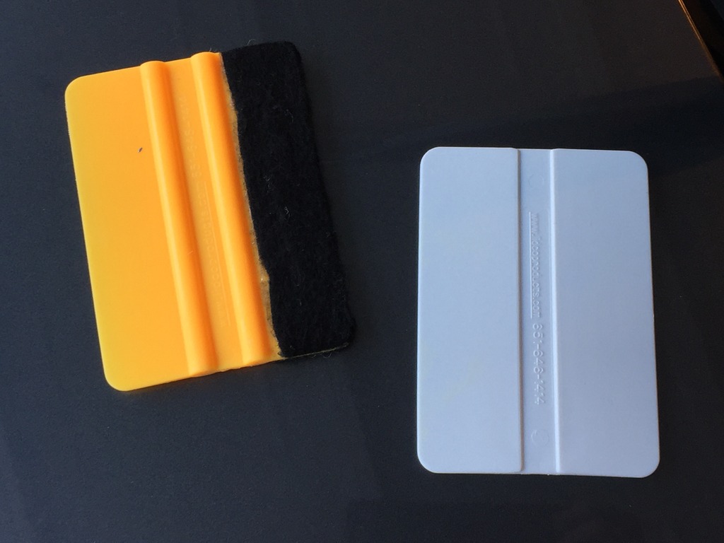
I also found a decal/wrapping squeegee is a huge help and makes the job very easy.
Everything exposed
AAB5CB7F-2F87-46B6-BB85-61271D1BBCE6_zpsxcfxn9dj.jpg Photo by apefactory | Photobucket
Use the plastic squeegee to lift the plastic cowl off the glass and slide the long end of the j-groove strip between the cowl and the glass. Move the squeegee along and install the strip as you go.
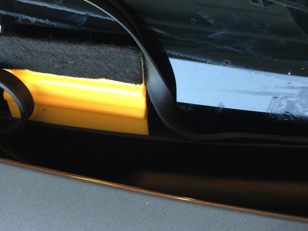
I used the felt side to push the strip flush and you can use a bit of protectant to lubricate the strip and make insertion easier too.
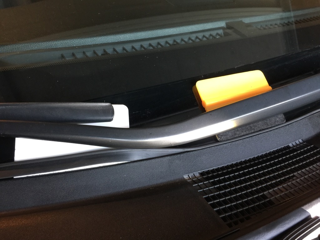
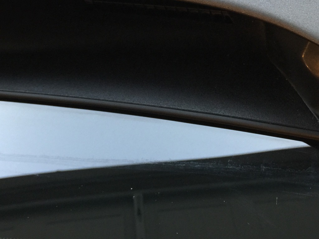
Done. Looks OEM.
I purchased the stripping from Amazon as all the ebay vendors were sold out.
https://www.amazon.com/gp/product/B0...?ie=UTF8&psc=1
I also found a decal/wrapping squeegee is a huge help and makes the job very easy.
Everything exposed
AAB5CB7F-2F87-46B6-BB85-61271D1BBCE6_zpsxcfxn9dj.jpg Photo by apefactory | Photobucket
Use the plastic squeegee to lift the plastic cowl off the glass and slide the long end of the j-groove strip between the cowl and the glass. Move the squeegee along and install the strip as you go.
I used the felt side to push the strip flush and you can use a bit of protectant to lubricate the strip and make insertion easier too.
Done. Looks OEM.
01-10-2017, 09:52 PM
#64
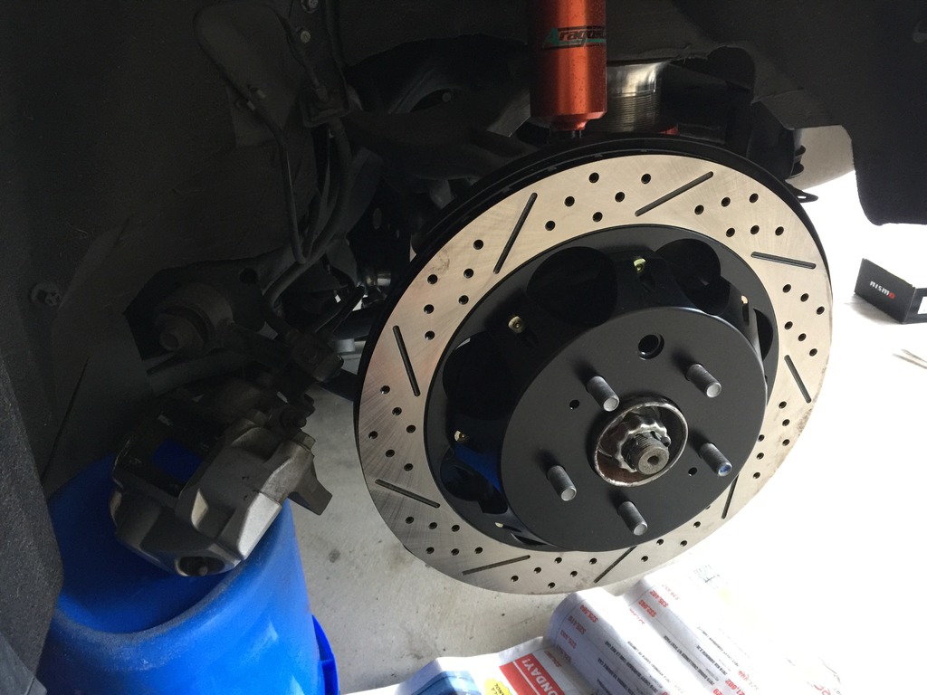
Ok got the brakes installed minus the braided lines. Was a much easier job than I thought it'd be, especially in the rear. Was a real piece of cake even with the cold temps I had to endure in an unheated garage (first world problem I know!). I had a fellow forum member stop by and offer encouragement for the first wheel and everything went smoothly. Except for the fact I installed the disks on the wrong side. I'll have to flip them this week and weekend.
Honestly, on the street, it isn't going to matter much. Regardless, I'll flip 'em.
I did a DIY for the rear rotors which I've copied and pasted below but it's also in the DIY section. There's one dark video on Youtube of a guy doing the rears on a 370Z and it made it look harder than it really was.
***NOTE, in the photos of the Z1 rotors installed, the leading edge of the slots, the part that'll come into contact with the pads first, is on the bottom. That's wrong, should be the top of the slot. This actually has to do with the curved vanes internally and not the slots themselves. It's simply a visual cue as to which way to install the rotors. The curved vane direction is more important.****
Since there isn't a DIY on changing out the rear rotors and pads for the Akebono brakes (Sport, IPL), I thought I'd go ahead and snap photos as I went through the installation today and post up a how to.
This is how I did things and it's only a guide. I suggest some experience is necessary along with a shop manual, the appropriate mechanical skills, etc...you do this at your own peril and I assume no responsibility nor intend for this to be an 100% correct guide. So do your homework.
First, it's not much more difficult than installing the front rotors and pads. There's one extra step and that's adjusting the parking brake. It's easy and I'l get to that shortly.
Time wise, it took me about two hours including cleanup and cleaning of the stock brake hardware parts. If you have new pins, springs and clips, it'll save you about 20 minutes.
I'm installing Z1 two-piece rear rotors but it's the same for any rotor make that bolts on like OEM.
Some of these steps are particular to those with an automatic G37.
Tools and supplies needed:
-3/8" or 1/2" torque wrench. You'll need two readings, 60ft. lbs. and 80ft. lbs so make sure your wrench can cover both.
-1/2" breaker bar
-19mm socket, short
-Three inch, 1/2" extension
-19mm crow's foot (optional)
-Short phillips head screwdriver
-1/2" ratcheting wrench
-19mm closed wrench (ratcheting or otherwise)
-small punch or thin screwdriver to push the caliper pins out
-dremel with a small bristle head for cleaning off rust
-dead blow hammer
-small pliers
-angle pliers (optional)
-Flat head screwdriver
-magnetic pan to hold small parts
-brake cleaner
-high temp grease
-anti-sieze
-small plastic container to soak brake hardware in cleaner
-lots of paper towels
-small flashlight
-crowbar (optional)
-piston spreader (optional)
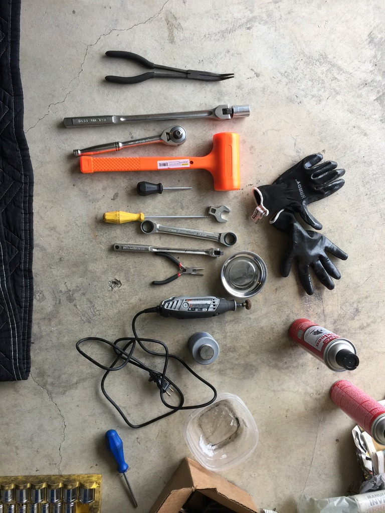
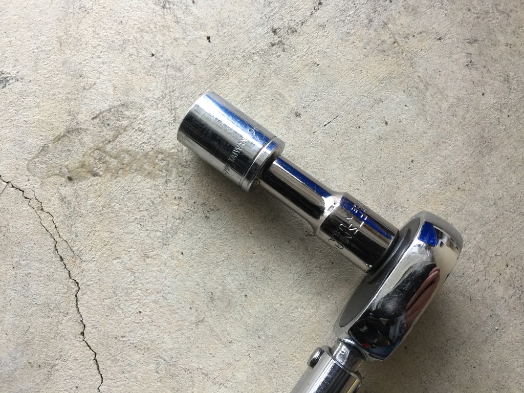
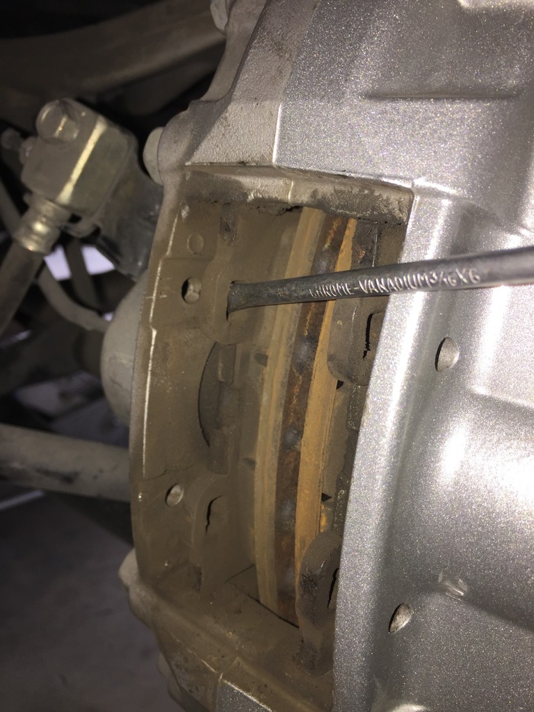
A note on the 19mm crow's foot. Because of the traction link, the lower caliper to upright bolt is tough to get to. I saw an installation where he used a crow's foot to torque to spec. I found I didn't need it. First, my 3/8" torque wrench didn't go up to 60ft.lbs. and I couldn't use the crow's foot wrench. I ended up putting on a 3" extension in between the 19mm socket and my 1/2" torque wrench and that worked just fine. So if you have a short extension, you should be ok without the crow's foot.
Here's a pic of what worked for me:
First, put wheel chocks under the front wheels. Loosen the rear lug nuts before jacking up the car. Jack up the rear (I slide my jack under the differential pumpkin) and put stands on either side of the car securely.
Remove the lugs, then the wheels. I have spacers on the rear so I needed to remove those too.
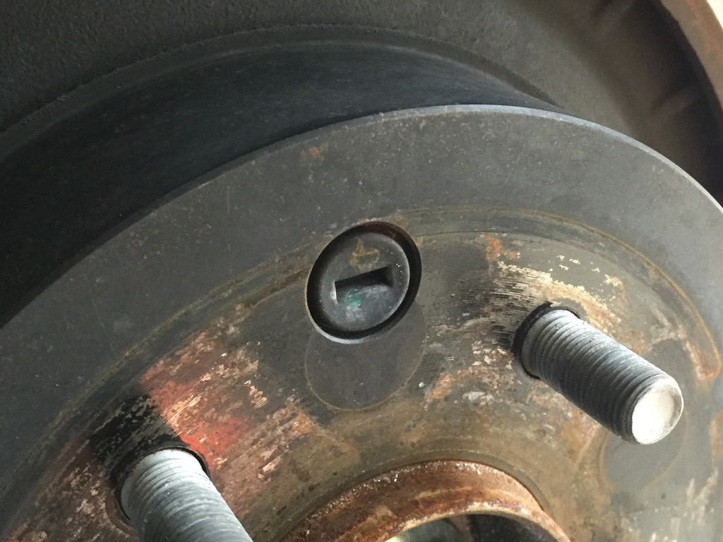
With my spacers off I could see this little job. It's a rubber grommet that seals the rear parking brake adjustment port. You can just use a flat head screwdriver to pop it out. Don't loose it and don't forget to re-install it!
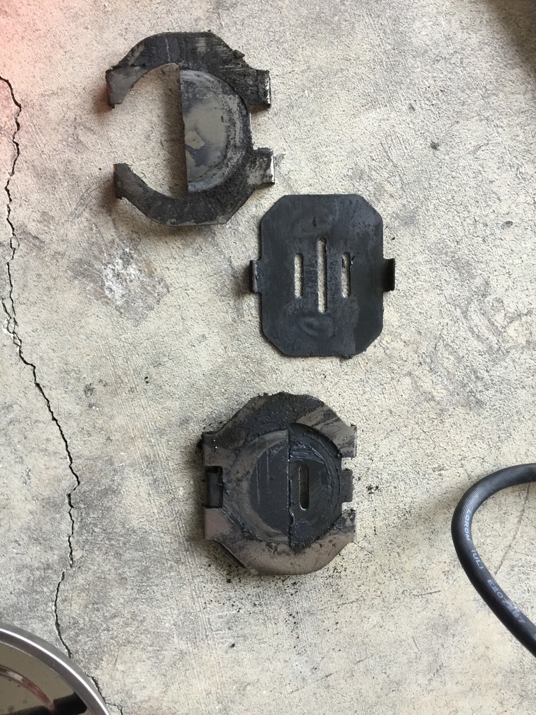
The next step is to remove the stock brake pad hardware and brake pads.
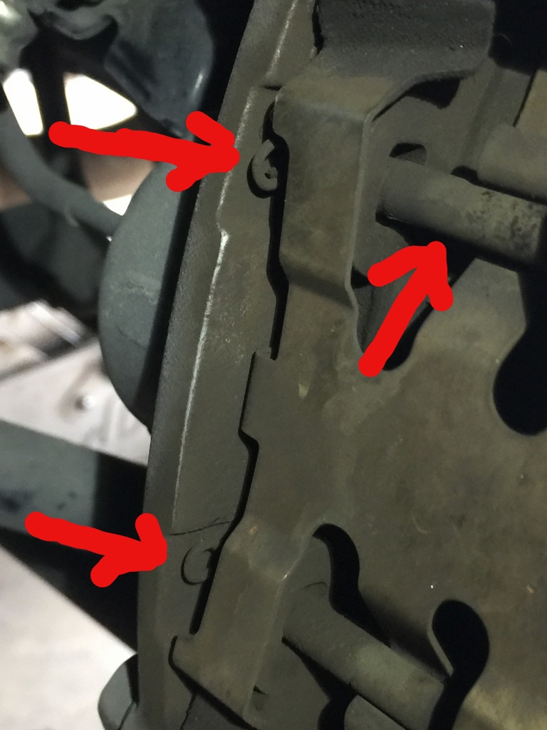
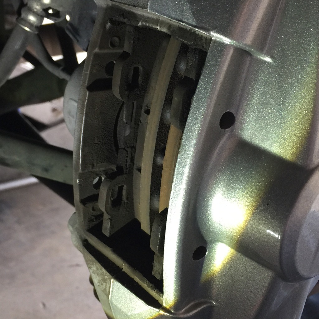
In the photo below, you can see the top of two small cotter clips (red arrows). Use a flashlight as it helps to see them. They're quite small. If you cannot see them, the third red arrow is one of two pins that keep the pads in the caliper. They rotate easily with a phillips head screwdriver. The head is on the inboard side so you'll need to use a short phillips head to rotate the pins until the cotter pins are visible. Pull them straight out. They come out easily so don't use a ton of force and send them flying. They'll be hard to find.
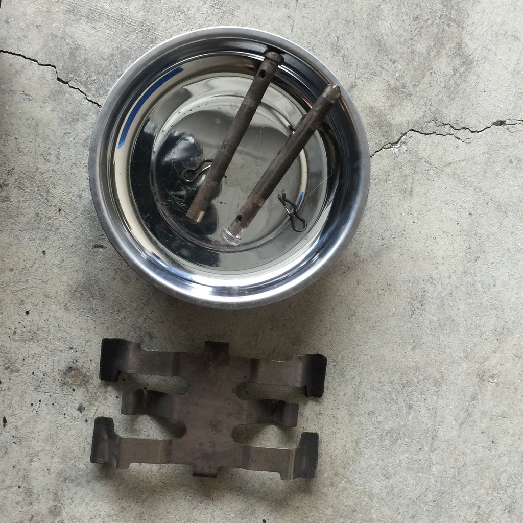
Here are the pins removed and secure in a magnetized dish so they can't get lost.
Once the clips are removed, you can then push the two caliper pins out. They push inwards. So you'll need to take your punch or screwdriver and push from the outside to the inboard side. They come out fairly easily.
Once those are removed, the brake pad spring will likely pop out. If not just lift it out with your fingers as there's nothing holding it in at this point.
You should have two clips, two pins and one spring per side.
With the caliper hardware removed, it's time to remove the brake pads. They can be a bit fussy and you may need to use a combination of a flat head screwdriver or various pliers inserted into the top and bottom brake pad holes on the pads themselves. Alternate between the two and wiggle them a bit and pry a bit if need be. They can get hung up on a rotor lip or on the shims but they will come out.
Pads are out! These are the stock Sport Akebono pads. They had plenty of life left at 30,000 miles. I put each pad in a separate bag and labeled them inboard and outboard. Note, the inboard pad will have the wear indicator clip, the outboard does not.
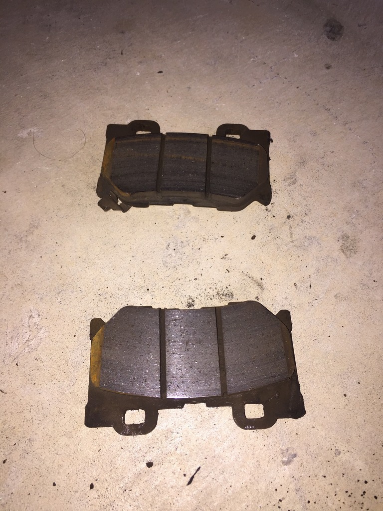
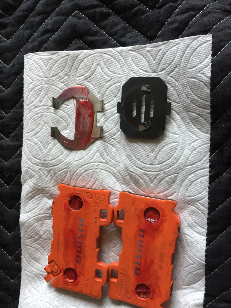
Take the backing plates or shims off the back of the stock pads. They only go on one way and take note of the marks made by the piston calipers. That'll help you determine what goes where when it's time to assemble. But they basically can only go on one way. At this point, I dumped all the hardware into a vat of brake cleaner to soak.
The next step is to remove the rear caliper. It's held on by TWO 19mm bolts that are torqued to 60ft lbs. I found it easiest to use a 19mm ratcheting wrench and hit it with a rubber mallet. Not too hard to get them off. In the photo, the camera is pointed from the inside to the outside so you're actually looking at the back (inboard side of the caliper).
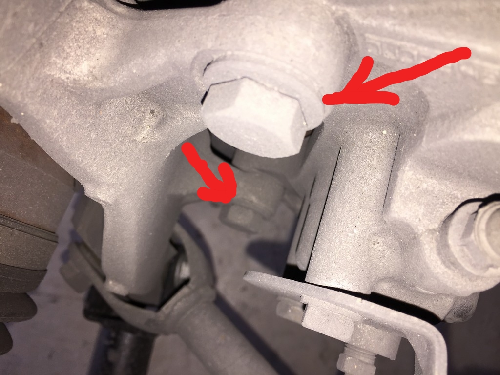
You can see the traction arm at the bottom of the photo next to the bottom caliper bolt. This is what causes you to either use a crow's foot or an extension.
Honestly, on the street, it isn't going to matter much. Regardless, I'll flip 'em.
I did a DIY for the rear rotors which I've copied and pasted below but it's also in the DIY section. There's one dark video on Youtube of a guy doing the rears on a 370Z and it made it look harder than it really was.
***NOTE, in the photos of the Z1 rotors installed, the leading edge of the slots, the part that'll come into contact with the pads first, is on the bottom. That's wrong, should be the top of the slot. This actually has to do with the curved vanes internally and not the slots themselves. It's simply a visual cue as to which way to install the rotors. The curved vane direction is more important.****
Since there isn't a DIY on changing out the rear rotors and pads for the Akebono brakes (Sport, IPL), I thought I'd go ahead and snap photos as I went through the installation today and post up a how to.
This is how I did things and it's only a guide. I suggest some experience is necessary along with a shop manual, the appropriate mechanical skills, etc...you do this at your own peril and I assume no responsibility nor intend for this to be an 100% correct guide. So do your homework.
First, it's not much more difficult than installing the front rotors and pads. There's one extra step and that's adjusting the parking brake. It's easy and I'l get to that shortly.
Time wise, it took me about two hours including cleanup and cleaning of the stock brake hardware parts. If you have new pins, springs and clips, it'll save you about 20 minutes.
I'm installing Z1 two-piece rear rotors but it's the same for any rotor make that bolts on like OEM.
Some of these steps are particular to those with an automatic G37.
Tools and supplies needed:
-3/8" or 1/2" torque wrench. You'll need two readings, 60ft. lbs. and 80ft. lbs so make sure your wrench can cover both.
-1/2" breaker bar
-19mm socket, short
-Three inch, 1/2" extension
-19mm crow's foot (optional)
-Short phillips head screwdriver
-1/2" ratcheting wrench
-19mm closed wrench (ratcheting or otherwise)
-small punch or thin screwdriver to push the caliper pins out
-dremel with a small bristle head for cleaning off rust
-dead blow hammer
-small pliers
-angle pliers (optional)
-Flat head screwdriver
-magnetic pan to hold small parts
-brake cleaner
-high temp grease
-anti-sieze
-small plastic container to soak brake hardware in cleaner
-lots of paper towels
-small flashlight
-crowbar (optional)
-piston spreader (optional)
A note on the 19mm crow's foot. Because of the traction link, the lower caliper to upright bolt is tough to get to. I saw an installation where he used a crow's foot to torque to spec. I found I didn't need it. First, my 3/8" torque wrench didn't go up to 60ft.lbs. and I couldn't use the crow's foot wrench. I ended up putting on a 3" extension in between the 19mm socket and my 1/2" torque wrench and that worked just fine. So if you have a short extension, you should be ok without the crow's foot.
Here's a pic of what worked for me:
First, put wheel chocks under the front wheels. Loosen the rear lug nuts before jacking up the car. Jack up the rear (I slide my jack under the differential pumpkin) and put stands on either side of the car securely.
Remove the lugs, then the wheels. I have spacers on the rear so I needed to remove those too.
With my spacers off I could see this little job. It's a rubber grommet that seals the rear parking brake adjustment port. You can just use a flat head screwdriver to pop it out. Don't loose it and don't forget to re-install it!
The next step is to remove the stock brake pad hardware and brake pads.
In the photo below, you can see the top of two small cotter clips (red arrows). Use a flashlight as it helps to see them. They're quite small. If you cannot see them, the third red arrow is one of two pins that keep the pads in the caliper. They rotate easily with a phillips head screwdriver. The head is on the inboard side so you'll need to use a short phillips head to rotate the pins until the cotter pins are visible. Pull them straight out. They come out easily so don't use a ton of force and send them flying. They'll be hard to find.
Here are the pins removed and secure in a magnetized dish so they can't get lost.
Once the clips are removed, you can then push the two caliper pins out. They push inwards. So you'll need to take your punch or screwdriver and push from the outside to the inboard side. They come out fairly easily.
Once those are removed, the brake pad spring will likely pop out. If not just lift it out with your fingers as there's nothing holding it in at this point.
You should have two clips, two pins and one spring per side.
With the caliper hardware removed, it's time to remove the brake pads. They can be a bit fussy and you may need to use a combination of a flat head screwdriver or various pliers inserted into the top and bottom brake pad holes on the pads themselves. Alternate between the two and wiggle them a bit and pry a bit if need be. They can get hung up on a rotor lip or on the shims but they will come out.
Pads are out! These are the stock Sport Akebono pads. They had plenty of life left at 30,000 miles. I put each pad in a separate bag and labeled them inboard and outboard. Note, the inboard pad will have the wear indicator clip, the outboard does not.
Take the backing plates or shims off the back of the stock pads. They only go on one way and take note of the marks made by the piston calipers. That'll help you determine what goes where when it's time to assemble. But they basically can only go on one way. At this point, I dumped all the hardware into a vat of brake cleaner to soak.
The next step is to remove the rear caliper. It's held on by TWO 19mm bolts that are torqued to 60ft lbs. I found it easiest to use a 19mm ratcheting wrench and hit it with a rubber mallet. Not too hard to get them off. In the photo, the camera is pointed from the inside to the outside so you're actually looking at the back (inboard side of the caliper).
You can see the traction arm at the bottom of the photo next to the bottom caliper bolt. This is what causes you to either use a crow's foot or an extension.
01-10-2017, 09:53 PM
#65
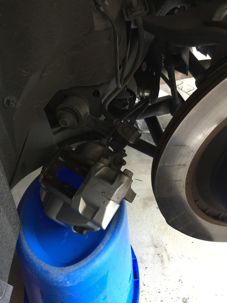
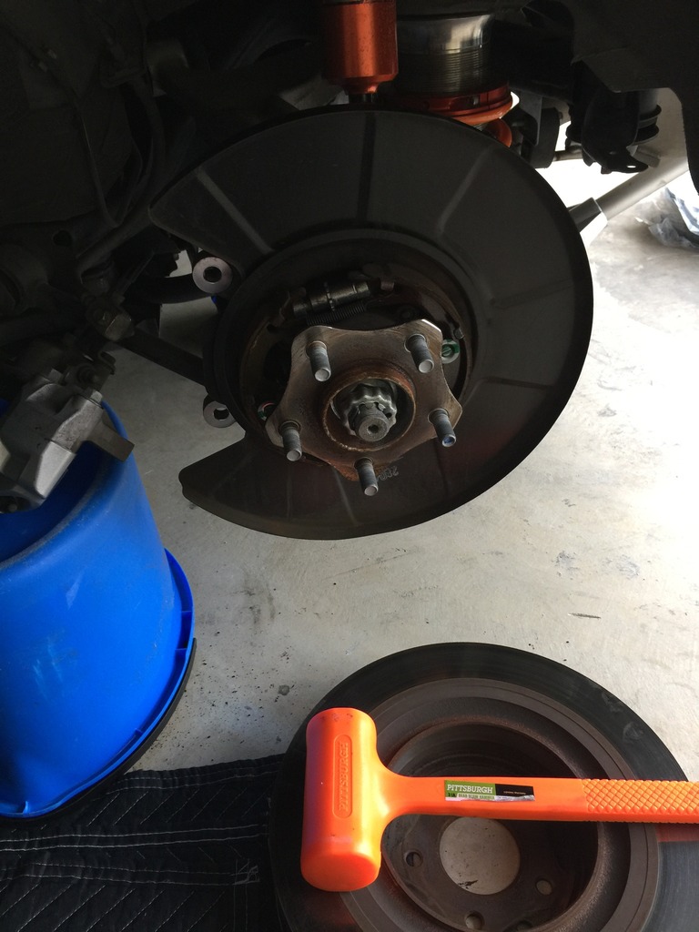
Once the two 19mm bolts are removed, the caliper will fall right off so be sure to support it.
You'll need a blue bucket a bit over a foot tall, turned upside down, to support the caliper and not put stress on the brake lines.
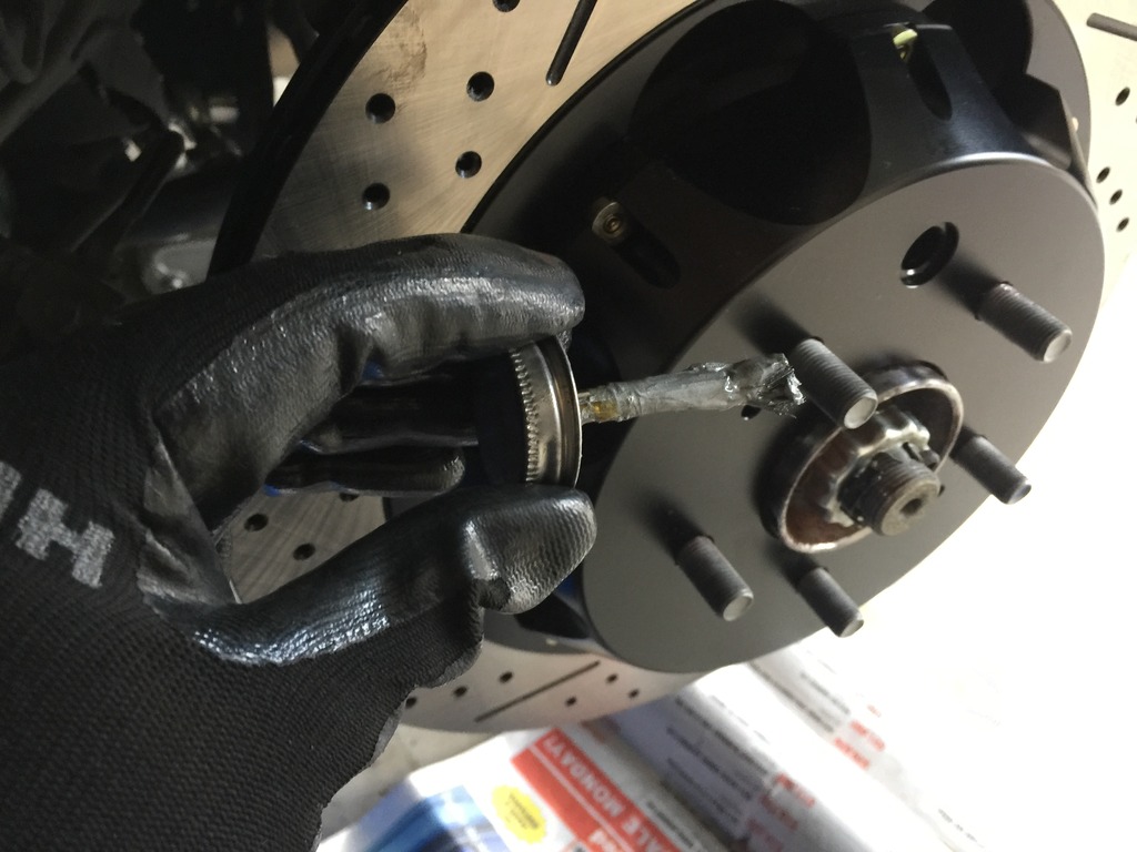
I'm going to cheat a bit here (we haven't gotten to this point) but it's helpful to see what the parking brake adjustment mechanism looks like.
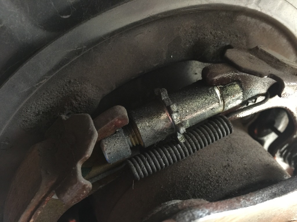
If your car has fairly low miles and isn't from the rust belt, the rotors may come off with a few hits of a dead blow hammer. Mine did and it was quite easy. I did not have to adjust the parking brake mechanism to full loose in order to take them off.
If you find the parking brake needs to be loosened, you'll need to do this now with a flat head screwdriver.
If you have a manual-equipped G, take it out of gear and make sure the parking brake is disengaged. Rotate the brake disk until the parking brake adjustment port (hole) allows you to see the adjuster with a flashlight.
If you have an auto-equipped car, you'll need to have your keys. Get in the driver's seat and DO NOT put your foot on the brake. Hit the start button twice until the accessories are all on but the engine is NOT on. THEN put your foot on the brake and shift the car into neutral. Make sure your lights are off Go back to the rear wheel and rotate the disk until you can see the brake adjuster through the access port. Go back and turn car off.
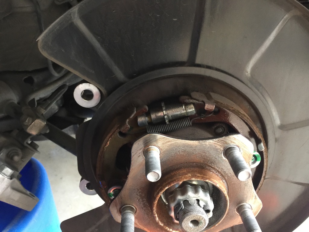
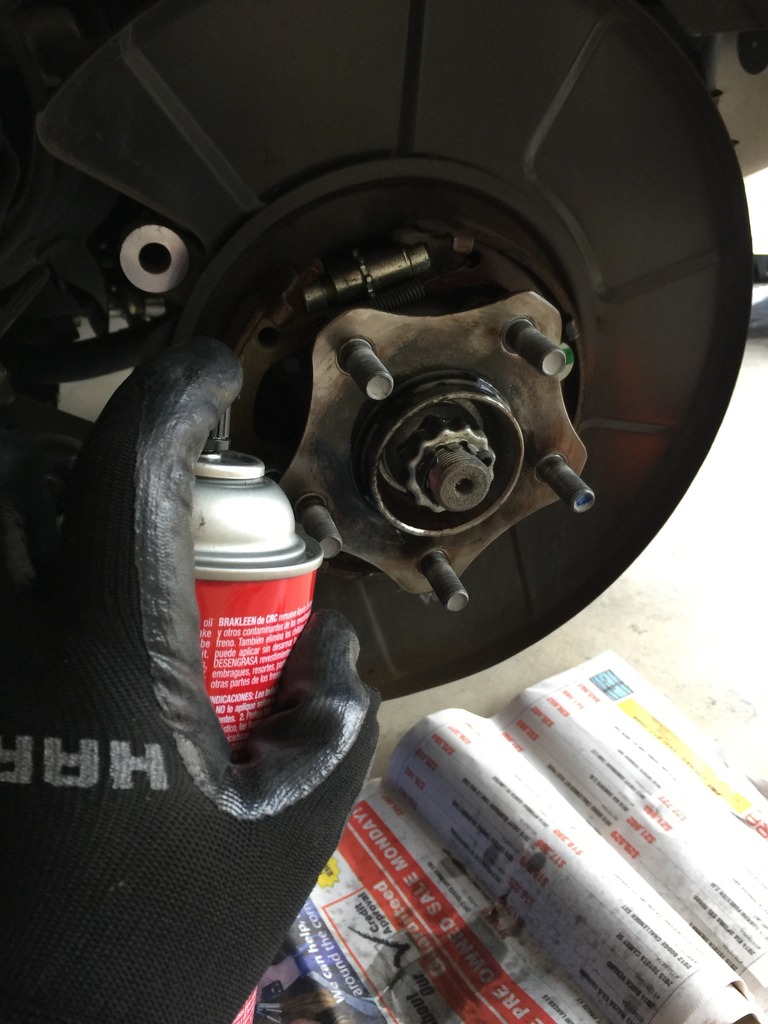
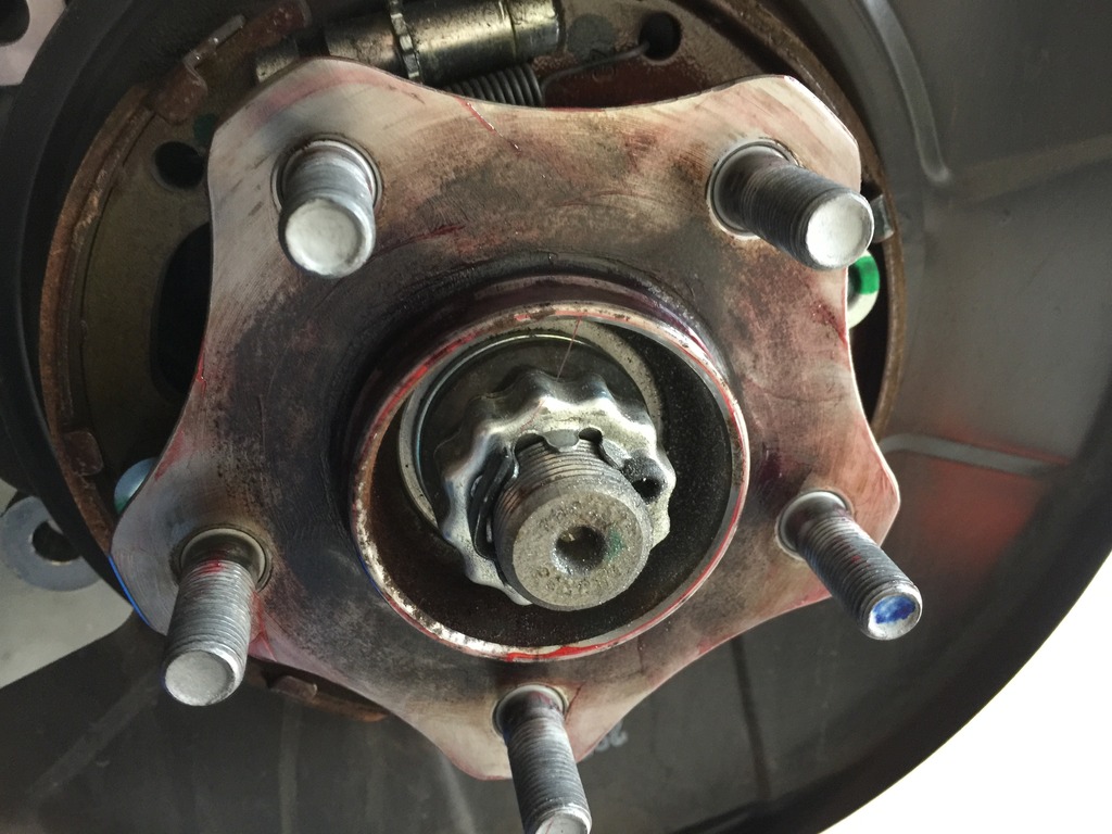
Let's look at that photo one more time. The adjuster is the thing in the middle with the teeth sticking out. It's basically a turnbuckle and you adjust it through the port with the flat head screwdriver by rotating it via the teeth. The spring below keeps it from rotating on its own so you need to get the screwdriver head in between the teeth and the spring. If I remember correctly, rotate it down to loosen the brake, up to tighten it. It may be the reverse. The gap visible on the left side will grow or shrink and you can see it through the port to figure out which way you need to turn it.
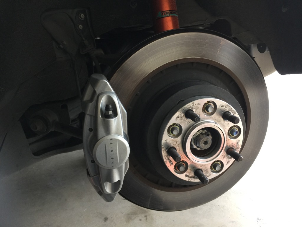
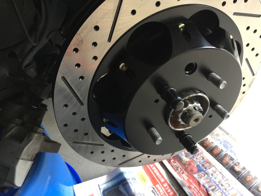
Here's the rear hub after taking off the rear brake disk. You'll want to clean it and remove the rust.
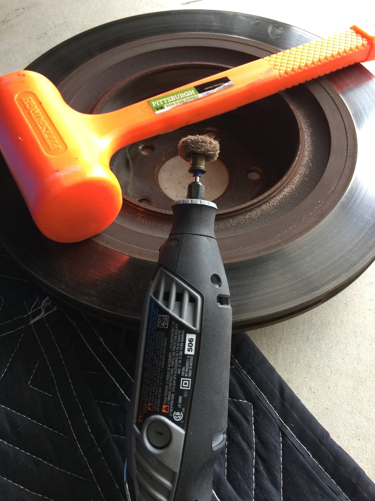
I used a dremel. There's something called a hub cleaning tool but they're expensive, like $40 and you'll use it maybe once in your lifetime. It's a cylinder, hollow in the middle, and attaches to your cordless drill. Has an abrasive disk on the end and you can slide it over the top of the wheel stud and clean the hub surface. The dremel, with the little abrasive disk on the end, worked just as well.
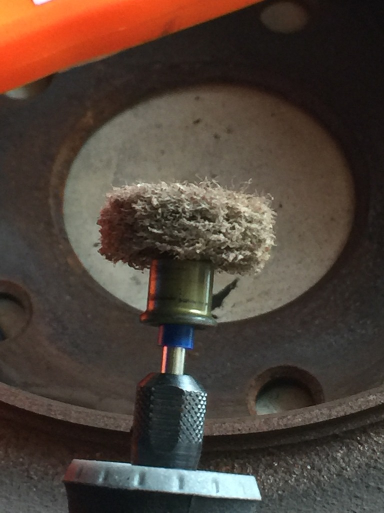
After scrubbing the face with the dremel, I spray it down with brake fluid and wipe everything off.
The next step is your first use of high temp grease. I wipe on a light coat with a clean finger and then wipe it off with a paper towel. It'll leave a very thin layer behind and it should help keep rust at bay. I have anodized aluminum hats so they won't bond to the steel hubs.
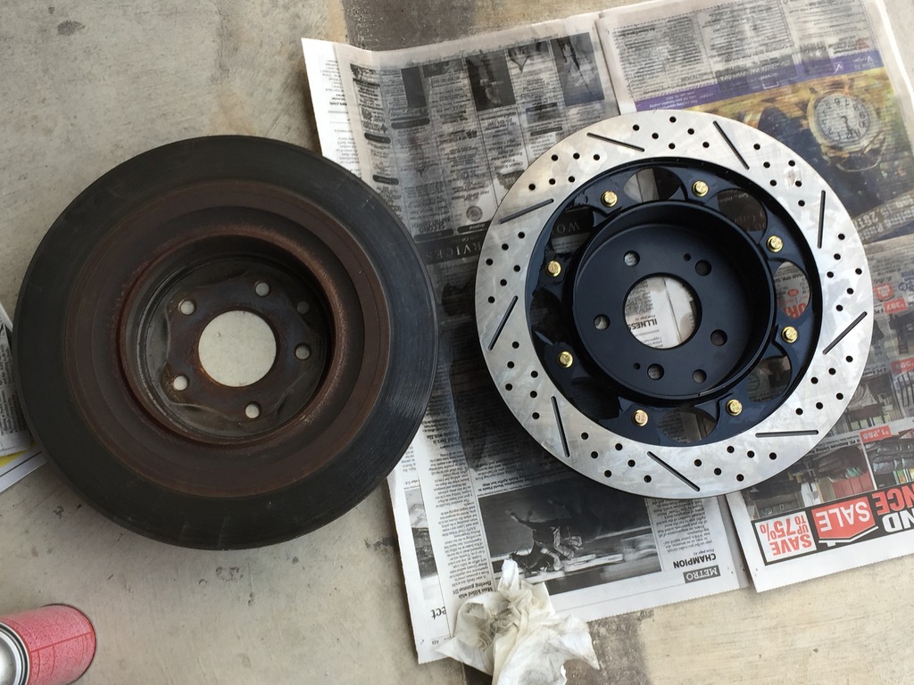
It's sexy time! Stock (duh) on the left, Z1 two-piece on the right. I think they're about five pounds lighter than the stock disks. The front Z1 disks are 10 pounds lighter.
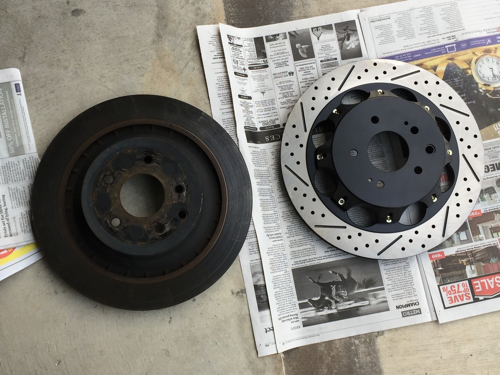
I put the new rotor on some newspaper and spray it down thoroughly, both sides, to remove any machining oil or other contaminants. I then wipe the disk faces off with clean paper towels.
Now that it's clean, install the disk on the hub/wheel studs and make sure the parking brake adjustment port is lined up with the adjuster.
I use anti-seize on the studs.
I then screw on two of the wheel nuts to make sure the brake disk is sitting squarely and firmly against the hub.
You're now ready to install your new (or used) pads and brake caliper hardware. I've had the hardware soaking so I remove all of it and wipe it down til it looks fairly clean. It's probably best just to purchase new hardware but no one had it in stock and I thought, just maybe, the Nismo pads would come with new hardware. They don't. My hardware was in good shape so I reused it.
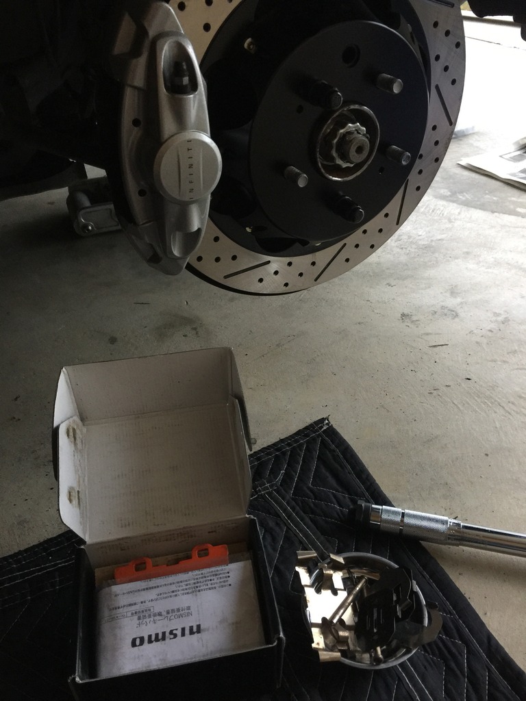
Business side of the Nismo rear pads.
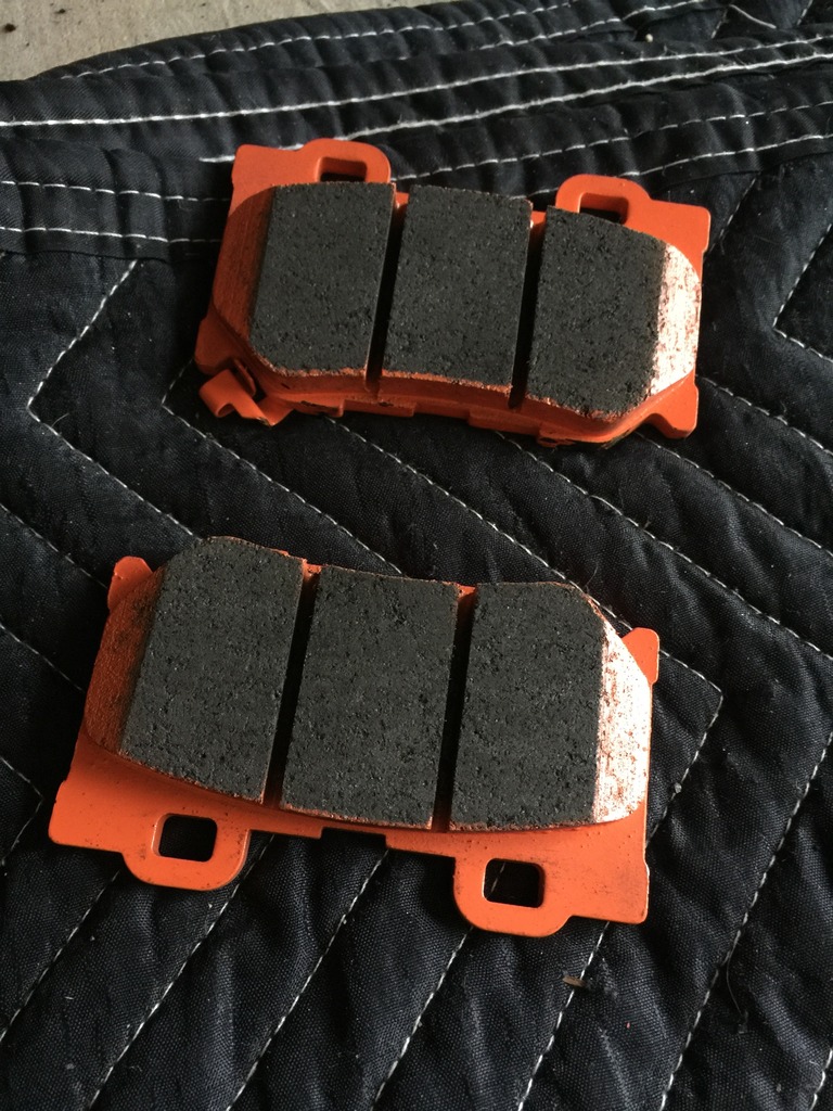
Nismo pads with the shims ready for installation.
I used high temp grease between the pads and the shims. The shims are two-piece and there's grease between them as well. I also put a very small amount on all four corners of the pad backing plate where the spring will touch it.
I didn't take any photos of the next step as it's too difficult to do both at the same time. The next step is to push the caliper pistons back into the caliper.
FIRST, pop your hood and open the brake master cylinder access door on the driver's side. Open your brake fluid reservoir.
Pushing the pistons back in will facilitate sliding the pads back in. If you're using new pads, they'll be thicker than the ones you took out and they won't just slide back in without pushing the pistons in first. I don't use a piston spreader, I just gingerly push them back in with the tools at hand. Mine were in good shape and slid in fairly easily.
Once that's done and you've reinstalled the shims onto your new pad, you can slide them back in. It'll take a bit of wiggling top to bottom and a gentle tap from a rubber mallet sometimes helps.
Success, pads in!
Once the pads are in, it's time to install the hardware in reverse order. Place the spring over the caliper opening and pads. Slide the pins in from the inboard to the outboard side. You'll go underneath the outer tabs and over the middle tab so you'll need to push that down as you slide the pin in. Again, it'll take a bit of wiggling to get it through both holes. Once the pins are all the way in, use the phillips head screwdriver to rotate them so the pin holes are accessible and you can slide the cotter pins back in. Do not forget to put them back in otherwise you could have catastrophic brake failure.
You're done! Re-install the wheel and torque the lugs to 80ft. lbs. Follow the bed-in procedure recommended by the manufacturer if there is one.
You'll need a blue bucket a bit over a foot tall, turned upside down, to support the caliper and not put stress on the brake lines.
I'm going to cheat a bit here (we haven't gotten to this point) but it's helpful to see what the parking brake adjustment mechanism looks like.
If your car has fairly low miles and isn't from the rust belt, the rotors may come off with a few hits of a dead blow hammer. Mine did and it was quite easy. I did not have to adjust the parking brake mechanism to full loose in order to take them off.
If you find the parking brake needs to be loosened, you'll need to do this now with a flat head screwdriver.
If you have a manual-equipped G, take it out of gear and make sure the parking brake is disengaged. Rotate the brake disk until the parking brake adjustment port (hole) allows you to see the adjuster with a flashlight.
If you have an auto-equipped car, you'll need to have your keys. Get in the driver's seat and DO NOT put your foot on the brake. Hit the start button twice until the accessories are all on but the engine is NOT on. THEN put your foot on the brake and shift the car into neutral. Make sure your lights are off
Go back to the rear wheel and rotate the disk until you can see the brake adjuster through the access port. Go back and turn car off.Let's look at that photo one more time. The adjuster is the thing in the middle with the teeth sticking out. It's basically a turnbuckle and you adjust it through the port with the flat head screwdriver by rotating it via the teeth. The spring below keeps it from rotating on its own so you need to get the screwdriver head in between the teeth and the spring. If I remember correctly, rotate it down to loosen the brake, up to tighten it. It may be the reverse. The gap visible on the left side will grow or shrink and you can see it through the port to figure out which way you need to turn it.
Here's the rear hub after taking off the rear brake disk. You'll want to clean it and remove the rust.
I used a dremel. There's something called a hub cleaning tool but they're expensive, like $40 and you'll use it maybe once in your lifetime. It's a cylinder, hollow in the middle, and attaches to your cordless drill. Has an abrasive disk on the end and you can slide it over the top of the wheel stud and clean the hub surface. The dremel, with the little abrasive disk on the end, worked just as well.
After scrubbing the face with the dremel, I spray it down with brake fluid and wipe everything off.
The next step is your first use of high temp grease. I wipe on a light coat with a clean finger and then wipe it off with a paper towel. It'll leave a very thin layer behind and it should help keep rust at bay. I have anodized aluminum hats so they won't bond to the steel hubs.
It's sexy time! Stock (duh) on the left, Z1 two-piece on the right. I think they're about five pounds lighter than the stock disks. The front Z1 disks are 10 pounds lighter.
I put the new rotor on some newspaper and spray it down thoroughly, both sides, to remove any machining oil or other contaminants. I then wipe the disk faces off with clean paper towels.
Now that it's clean, install the disk on the hub/wheel studs and make sure the parking brake adjustment port is lined up with the adjuster.
I use anti-seize on the studs.
I then screw on two of the wheel nuts to make sure the brake disk is sitting squarely and firmly against the hub.
You're now ready to install your new (or used) pads and brake caliper hardware. I've had the hardware soaking so I remove all of it and wipe it down til it looks fairly clean. It's probably best just to purchase new hardware but no one had it in stock and I thought, just maybe, the Nismo pads would come with new hardware. They don't. My hardware was in good shape so I reused it.
Business side of the Nismo rear pads.
Nismo pads with the shims ready for installation.
I used high temp grease between the pads and the shims. The shims are two-piece and there's grease between them as well. I also put a very small amount on all four corners of the pad backing plate where the spring will touch it.
I didn't take any photos of the next step as it's too difficult to do both at the same time. The next step is to push the caliper pistons back into the caliper.
FIRST, pop your hood and open the brake master cylinder access door on the driver's side. Open your brake fluid reservoir.
Pushing the pistons back in will facilitate sliding the pads back in. If you're using new pads, they'll be thicker than the ones you took out and they won't just slide back in without pushing the pistons in first. I don't use a piston spreader, I just gingerly push them back in with the tools at hand. Mine were in good shape and slid in fairly easily.
Once that's done and you've reinstalled the shims onto your new pad, you can slide them back in. It'll take a bit of wiggling top to bottom and a gentle tap from a rubber mallet sometimes helps.
Success, pads in!
Once the pads are in, it's time to install the hardware in reverse order. Place the spring over the caliper opening and pads. Slide the pins in from the inboard to the outboard side. You'll go underneath the outer tabs and over the middle tab so you'll need to push that down as you slide the pin in. Again, it'll take a bit of wiggling to get it through both holes. Once the pins are all the way in, use the phillips head screwdriver to rotate them so the pin holes are accessible and you can slide the cotter pins back in. Do not forget to put them back in otherwise you could have catastrophic brake failure.
You're done! Re-install the wheel and torque the lugs to 80ft. lbs. Follow the bed-in procedure recommended by the manufacturer if there is one.
The following users liked this post:
blnewt (01-11-2017)


The following users liked this post:
Ape Factory (01-10-2017)
01-11-2017, 09:20 AM
#71
Administrator

iTrader: (9)
 I mean, who does that? LOL
And yes, those new rotors definitely "look the biz" behind your rims. They're gorgeous. I'd love to see more pictures of these rotors installed, from a few different distance perspectives please, both fronts and rears. I ask because slotted, 2-piece rotors from Z1 are most certainly on my list when the day comes to replace the Akebonos, and you've got the photo skills to deliver.
Also... I have to ask this, just because. How the fck are you doing all these mods all at once?
 It's got to be like a full-time job. Certainly seems like a full-time salary commitment, too.
Trying to keep up reading your thread is exhausting, and more than a little bit humbling.
Last edited by Rochester; 01-11-2017 at 12:58 PM.
The following users liked this post:
Ape Factory (08-05-2017)
01-24-2017, 10:38 AM
#74
I'm not planning on making a dyno run untuned unfortunately. I did a/f readings and while they're better than they were with just intakes, it's still very rich from about 4K on up so I don't see the point.
I did do two more brake mods, Z1 premium braided brake lines and Z1 master cylinder brace.
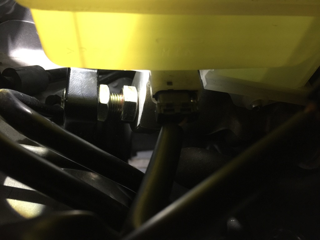
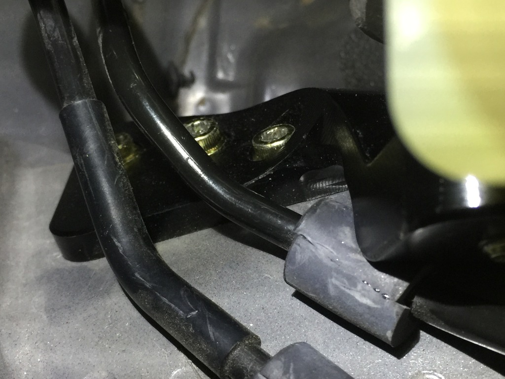
I actually managed to get all three bolts in the brace but it was a huge PITA. I half jokingly say f*ck you Z1 for even making this and the other half of the FU goes to Nissan for brake lines that have what look to be wholly unnecessary bends in all the brake lines coming off the MC. At the very least Z1 should include the damn 5mm extended allen socket and pay YOU for even installing it. But I applaud the effort in producing something like this so they get a half joking rating
I did do two more brake mods, Z1 premium braided brake lines and Z1 master cylinder brace.
I actually managed to get all three bolts in the brace but it was a huge PITA. I half jokingly say f*ck you Z1 for even making this and the other half of the FU goes to Nissan for brake lines that have what look to be wholly unnecessary bends in all the brake lines coming off the MC. At the very least Z1 should include the damn 5mm extended allen socket and pay YOU for even installing it. But I applaud the effort in producing something like this so they get a half joking rating