Calling nav swappers
 06-02-2013, 05:27 PM
#16
Registered User
Thread Starter

Join Date: Sep 2012
Posts: 43
Likes: 0
Received 0 Likes
on
0 Posts
@Modme. I can only see the physical connector on the CCM. I need to find the other wires for the camera so I can tap them. In any event, I finished the main part of the swap, just not the camera. So interesting things popped up. The airbag light is now blinking, the check engine light is on and so is the TPMS. I these should just be resets, but was wondering if anybody else who did the swap has seen these lights come on.
 06-03-2013, 06:55 PM
#17
Registered User
Thread Starter
Join Date: Sep 2012
Posts: 43
Likes: 0
Received 0 Likes
on
0 Posts
**UPDATE** @Modme, I now see what you were talking about and I've completed the wiring and everything works as expected. With that, I'm now officially part of the "Nav Swappers Club".
Some shout outs to those who helped me along the way include @Modme, @michg37 and @mystikal, thanks guys!
Some shout outs to those who helped me along the way include @Modme, @michg37 and @mystikal, thanks guys!
07-11-2016, 12:51 AM
#18
Registered Member

Hey reviving this thread. Not sure if any of these guys are still around but what ground did you use for the camera? Did you run a new wire from the AV unit to the camera?
08-27-2016, 02:03 AM
#19
Registered Member

re-reviving thread again. anyone else find a good diy write for this swap? looking to do this project with my 08 coupe with nav. seen a lot of helpful posts from modme so far...thanks for all your helpful information brother. thanks in advance to anyone for their input.
08-28-2016, 11:07 AM
#20
Registered User

re-reviving thread again. anyone else find a good diy write for this swap? looking to do this project with my 08 coupe with nav. seen a lot of helpful posts from modme so far...thanks for all your helpful information brother. thanks in advance to anyone for their input.
03-20-2018, 10:25 PM
#21

Bringing this one back from the dead lol...
I have an 08 g37s Bose and nav... and I'm seriously considering this swap... really want the upgraded screen and other stuff...Thank you to everyone who shared information... This thread pretty much has everything you need and like has been said you need to be able to read wiring diagrams... Theres never going to be a step by step diy sticky for something like this lol...
But I do have one question... For anyone who has done this or is familiar with the factory radio...
Do you think it could be done without the newer nav av unit pigtails? Finding the pigtails seems to be impossible... I'm not sure on the pin size but I think you can buy individual pin connectors...
Modme stated the need for a gvif cable... a google search seems to come up with that cable... And the usb should be easy... Just the pigtails are tough to find without buying the whole harness..
Thanks
03-21-2018, 11:26 AM
#22


Looking over my old notes:
Being that you already have NAV, you might be able to use the same connectors. My Coupe did not originally have NAV so I had no choice but to source some connectors from eBay. There was one connector that was, for whatever reason, next to impossible to find: a 40-pin connector (TH40FW-NH, M209) but in the end I found one. Just compare the two diagrams (your car and the donor) and see which connectors match up and which ones you may need.
Important to note that the sound signal/Bose Amp wires uses different sized PINS/TERMINALS. These wires have to be moved to a different connector (M81/M208, TH18FW-CS2) and the pins WILL NOT FIT. You will have to splice these wires.
The GVIF cable for the display was easy to source. P/N: 28098-JJ90B, about $20.
The USB cable was NOT available anywhere, Infiniti or Nissan, and I looked forever on eBay until I came across one off a M35. Keep in mind I did this swap almost 2 years ago so surplus parts/supplies should be more readily available.
As long as you are knowledgeable reading wiring diagrams you should not have any problems. The actual swap took me about 2 days and my only regret was not doing it sooner.
Another important note: Follow the pinouts on the wiring diagram, NOT the wire color!
Hope some of this helps. If you have any additional questions just ask away!
Last edited by ILM-NC G37S; 03-21-2018 at 12:31 PM. Reason: Clarification
03-21-2018, 09:25 PM
#23
Looking over my old notes:
Being that you already have NAV, you might be able to use the same connectors. My Coupe did not originally have NAV so I had no choice but to source some connectors from eBay. There was one connector that was, for whatever reason, next to impossible to find: a 40-pin connector (TH40FW-NH, M209) but in the end I found one. Just compare the two diagrams (your car and the donor) and see which connectors match up and which ones you may need.
Important to note that the sound signal/Bose Amp wires uses different sized PINS/TERMINALS. These wires have to be moved to a different connector (M81/M208, TH18FW-CS2) and the pins WILL NOT FIT. You will have to splice these wires.
The GVIF cable for the display was easy to source. P/N: 28098-JJ90B, about $20.
The USB cable was NOT available anywhere, Infiniti or Nissan, and I looked forever on eBay until I came across one off a M35. Keep in mind I did this swap almost 2 years ago so surplus parts/supplies should be more readily available.
As long as you are knowledgeable reading wiring diagrams you should not have any problems. The actual swap took me about 2 days and my only regret was not doing it sooner.
Another important note: Follow the pinouts on the wiring diagram, NOT the wire color!
Hope some of this helps. If you have any additional questions just ask away!
Being that you already have NAV, you might be able to use the same connectors. My Coupe did not originally have NAV so I had no choice but to source some connectors from eBay. There was one connector that was, for whatever reason, next to impossible to find: a 40-pin connector (TH40FW-NH, M209) but in the end I found one. Just compare the two diagrams (your car and the donor) and see which connectors match up and which ones you may need.
Important to note that the sound signal/Bose Amp wires uses different sized PINS/TERMINALS. These wires have to be moved to a different connector (M81/M208, TH18FW-CS2) and the pins WILL NOT FIT. You will have to splice these wires.
The GVIF cable for the display was easy to source. P/N: 28098-JJ90B, about $20.
The USB cable was NOT available anywhere, Infiniti or Nissan, and I looked forever on eBay until I came across one off a M35. Keep in mind I did this swap almost 2 years ago so surplus parts/supplies should be more readily available.
As long as you are knowledgeable reading wiring diagrams you should not have any problems. The actual swap took me about 2 days and my only regret was not doing it sooner.
Another important note: Follow the pinouts on the wiring diagram, NOT the wire color!
Hope some of this helps. If you have any additional questions just ask away!
Thank you!
Couple questions...
What is the deal with the USB cable? Is it a proprietary Cable? Maybe some pin molex connectors could be used with a female usb cable?
and as I start looking for hardware... Up to what years would be compatible with my car? 2013?
Thanks again
03-22-2018, 10:48 AM
#24
The USB and the GVIF cables use Hirose-type connectors, not your standard molex.
Here is the GVIF/display cable:
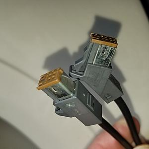
The USB is similar but it has a blue connector on one end (AV side) and a green connector at the USB jack/port side.
As for years, my donor was a 2014 Q60 that I found on eBay for around $250 for the display and AV unit. Anything 2010-2015 should work- obviously the "newer" the better.
Because you already have NAV, all you should need is the display, AV unit, USB port for the center console, and any necessary wiring connectors.
03-22-2018, 11:57 AM
#25


You can make the cable; its what I did for my swap. Parts to make it can be found online (i bought mine on Digi-Key) and they are:
H123550-ND
H124518CT-ND
H124508TR-ND
H123552-ND
H123551-ND
H123544-ND
H123543-ND
H124510TR-ND
Female end:
H122498CT-ND
I bought double over everything needed just to be safe and just used some unused USB cable I had laying around for the cable itself. It cost less then $25 to make two cables.
H123550-ND
H124518CT-ND
H124508TR-ND
H123552-ND
H123551-ND
H123544-ND
H123543-ND
H124510TR-ND
Female end:
H122498CT-ND
I bought double over everything needed just to be safe and just used some unused USB cable I had laying around for the cable itself. It cost less then $25 to make two cables.
03-23-2018, 10:41 PM
#26
Great information! You guys rock!
Thank you so much! I feel alot better about taking this on now...
Now time to start looking for hardware... Looking in ebay it looks like this shouldn't cost to much....
Thank you so much! I feel alot better about taking this on now...
Now time to start looking for hardware... Looking in ebay it looks like this shouldn't cost to much....
03-27-2018, 12:06 AM
#27
Just some info for anyone looking to do this...
I noticed that several units on ebay have the plugs in the unit and cut... Which may be helpfull... I noticed this after looking at the pictures the sellers post...
Some had less than half an inch of wire... But even at half an inch it's a big help...
Just a little fyi
I noticed that several units on ebay have the plugs in the unit and cut... Which may be helpfull... I noticed this after looking at the pictures the sellers post...
Some had less than half an inch of wire... But even at half an inch it's a big help...
Just a little fyi
03-27-2018, 04:59 PM
#28
Just having the connectors will be a huge bonus. Save a lot of time cutting-and-splicing/soldering/whichever route you take.
One cautionary word of advice: there are two connectors for the ACC Amp (plastic rectangular box mounted on AV unit. These connectors are IDENTICAL and also match one connector for the AV unit. It is EXTREMELY easy to mix these three connectors up. I marked the three connectors with a Sharpie to ensure they went in the location.
One cautionary word of advice: there are two connectors for the ACC Amp (plastic rectangular box mounted on AV unit. These connectors are IDENTICAL and also match one connector for the AV unit. It is EXTREMELY easy to mix these three connectors up. I marked the three connectors with a Sharpie to ensure they went in the location.
04-28-2018, 01:45 PM
#29

Just having the connectors will be a huge bonus. Save a lot of time cutting-and-splicing/soldering/whichever route you take.
One cautionary word of advice: there are two connectors for the ACC Amp (plastic rectangular box mounted on AV unit. These connectors are IDENTICAL and also match one connector for the AV unit. It is EXTREMELY easy to mix these three connectors up. I marked the three connectors with a Sharpie to ensure they went in the location.
One cautionary word of advice: there are two connectors for the ACC Amp (plastic rectangular box mounted on AV unit. These connectors are IDENTICAL and also match one connector for the AV unit. It is EXTREMELY easy to mix these three connectors up. I marked the three connectors with a Sharpie to ensure they went in the location.
I'm in the process of gathering parts and documenting the wiring for this effort.
I think I have most of what I need and have sourced mating connectors to make my own harness from japan (can't find them in the US...)
Do you have the wiring pinout for the camera?
And do you have any notes on what happens with the following wiring?
M87 (G35 07)
PIN COLOR Signal
21 B GND
22 Y BATTERY
23 B GND
24 Y BATTERY
25 V ACC
these don't appear to get re-used. I'm still trying to trace back through the diagrams though.
Also in M87 to M210 (G37 2010) pins 91 75 92 76 (AV COMM H/L) are duplicated. Do you recall which pin in M87 goes to which in M210?
Thanks for any help you can provide!
04-28-2018, 08:28 PM
#30
Not sure how much help I can offer but will do my best. Keep in mind that any information I provide is based on a G37 COUPE '08/'14. Wiring MAY BE different for the Vert and likely different from the G35. Double check your own car/components/wiring. That said:
First, I did not have a M87 Connector as I originally did not have NAV. However, based on the FSM for 2008 G37 Coupe Bose w/NAV:
Pins 22&24 (BAT) are tied to M80 Pin 19
Pins 21&23 (GND) are standard ground
Pin 25 (ACC) ties to M80 Pin 7
Apparently the older system needed multiple voltage sources/signals? All you will likely need are M80 Pins 7 (ACC) 19 (+), and 20 (GND).
M210 Pins:
91 to M85 Pin 88: AV COM H
75 to M85 Pin 89: AV COM L
---------------------------
92 to M85 Pin 90: AV COM H
76 to M85 Pin 91: AV COM L
The above are pairs, do NOT mix and match.
Camera:
Display M75 Pin 7: CAM SHIELD
Display M75 Pin 8: CAM IMAGE SIGNAL (yellow wire at camera)
Headunit M209 Pin 22: CAM PWR (white wire at camera)
Headunit M209 Pin 42: CAM GND (black wire at camera)
Hope this helps!